4-wheel Car Driver L293D Smart Car Driving Module/H-bridg
SKU: LC-motor-293-4
Overview
Overview
LC-motor-293-4 is four channel DC motor driving module .It adopts new original L293D chip , High quality aluminum electrolytic capacitor,STM manufacturing to enable working stable. It can drive 4ways 3-6V DC motor. And it also provide 5V power to MCU through its 5V output interface.(as long as output is below 7V)
Parameters
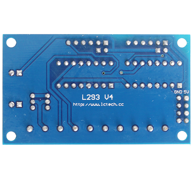
1.Chipset :L293D dual H-bridge DC motor driving chip
2.Peak current of driving part: 0.5A
3.Operating working current of logic part: 0-36mA
4.Max power consumption: 20W
5.Voltage range of driving part end: +5V-+16V (If you need to take power from the board, voltage range is +7V to +16V )
6.Input voltage range of signal controller: (IN1 IN2 IN3 IN4 IN5 IN6 IN7 IN8)
Low level: -0.3V<vin<1.5V
High level: 2.3V<vin<5V
7.Input voltage range of enable end (EN1 EN2 EN3 EN4)
Low level: -0.3V<vin<1.5V
High level: 2.3V<vin<5V
8.Storage temperature: -25C to +130 degree
9.Other extension :indicator for direction control, port for taking power from board )
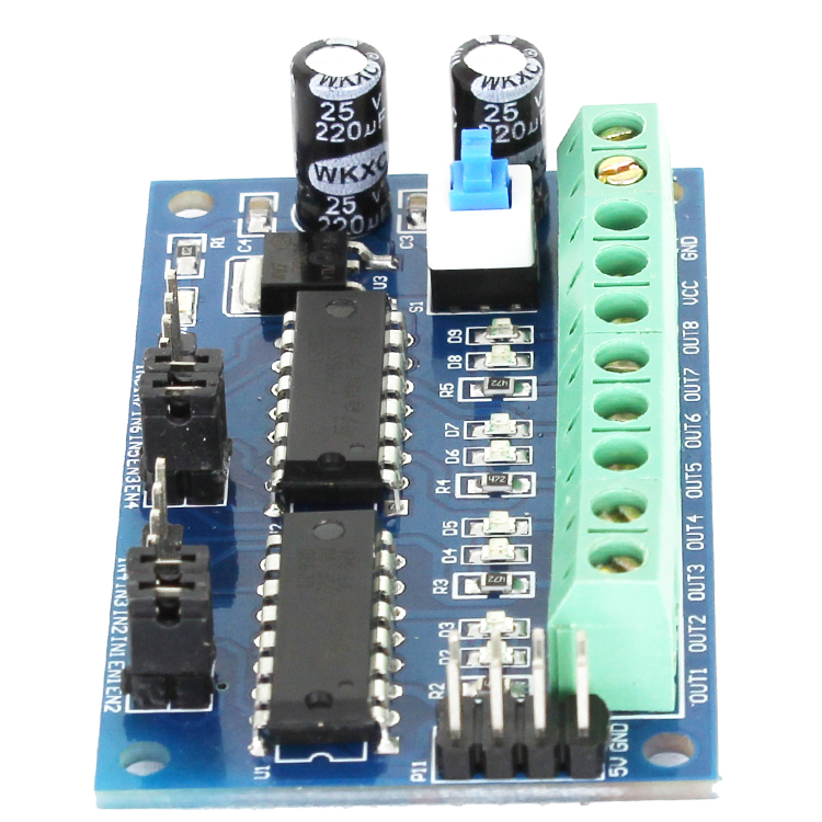
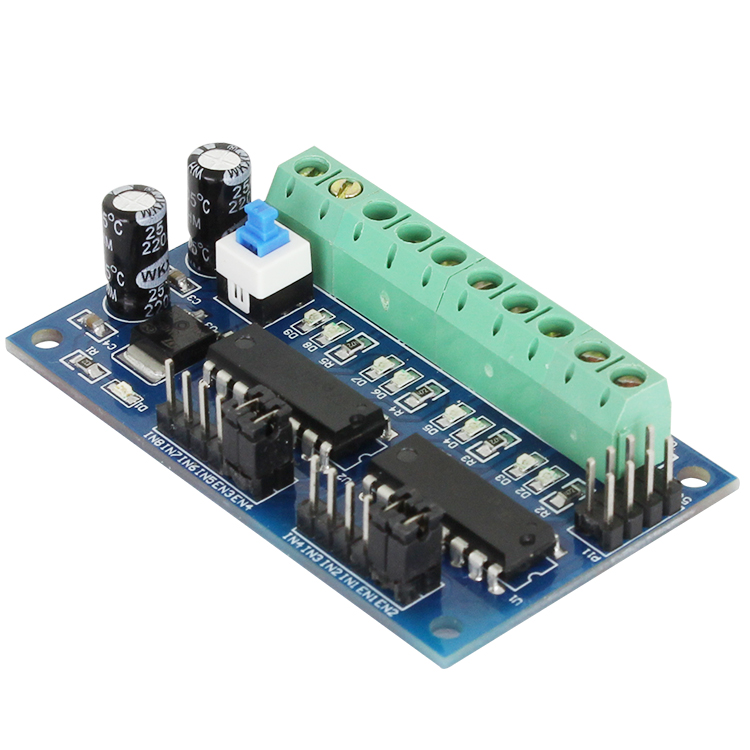
Interface instruction
VCC: Positive of power supply GND: negative for power supply
OUT1,OUT2: connector of motor 1 OUT3 OUT4: connector of motor 2
OUT5 OUT6: connect of motor 3 OUT7 OUT8: connector of motor 4
IN1-IN8: logic control end for motor IN1/IN2: control motor 2
IN3/IN4: control motor 1 IN5/IN6: control motor 4
IN7/IN8: control motor 3 EN1: enable end for motor 1
EN2: enable end for motor 2 EN3 enable end for motor 3
EN4: enable end for motor 4 S1: power switch
P11: 4 channel output 5V
Guide for operation
EN is valid on high level.Its control method and DC motor statue for motor 1 is as below:
1.Chipset :L293D dual H-bridge DC motor driving chip
2.Peak current of driving part: 0.5A
3.Operating working current of logic part: 0-36mA
4.Max power consumption: 20W
5.Voltage range of driving part end: +5V-+16V (If you need to take power from the board, voltage range is +7V to +16V )
6.Input voltage range of signal controller: (IN1 IN2 IN3 IN4 IN5 IN6 IN7 IN8)
Low level: -0.3V<vin<1.5V
High level: 2.3V<vin<5V
7.Input voltage range of enable end (EN1 EN2 EN3 EN4)
Low level: -0.3V<vin<1.5V
High level: 2.3V<vin<5V
8.Storage temperature: -25C to +130 degree
9.Other extension :indicator for direction control, port for taking power from board )
Interface instruction
VCC: Positive of power supply GND: negative for power supply
OUT1,OUT2: connector of motor 1 OUT3 OUT4: connector of motor 2
OUT5 OUT6: connect of motor 3 OUT7 OUT8: connector of motor 4
IN1-IN8: logic control end for motor IN1/IN2: control motor 2
IN3/IN4: control motor 1 IN5/IN6: control motor 4
IN7/IN8: control motor 3 EN1: enable end for motor 1
EN2: enable end for motor 2 EN3 enable end for motor 3
EN4: enable end for motor 4 S1: power switch
P11: 4 channel output 5V
Guide for operation
EN is valid on high level.Its control method and DC motor statue for motor 1 is as below:
| IN1 | IN2 | EN1 | MOTOR |
| 0 | 0 | 0 | No rotation |
| 0 | 1 | 0 | No rotation |
| 1 | 0 | 0 | No rotation |
| 1 | 1 | 0 | No rotation |
| 0 | 0 | 1 | No rotation |
| 0 | 1 | 1 | Forward rotation |
| 1 | 0 | 1 | Revise rotation |
| 1 | 1 | 1 | No rotation |