ICL8038 Low and Medium Frequency Signal Source Waveform Sign
Overview
The LC ICL8038 module is designed for common frequency ranges. It is adjustable from 5 gears and generates low-distortion triangular waves, square and sine waves from 10Hz to 450KHz. Sine wave can be used for test signals, drive signals, carrier frequency signals, etc; square wave can be used for switching signals, trigger signals, etc; triangular wave is mainly used for scanning signals.
The LC ICL8038 module is designed for common frequency ranges. It is adjustable from 5 gears and generates low-distortion triangular waves, square and sine waves from 10Hz to 450KHz. Sine wave can be used for test signals, drive signals, carrier frequency signals, etc; square wave can be used for switching signals, trigger signals, etc; triangular wave is mainly used for scanning signals.
Function features
1.Working voltage: 12V ~ 15V
2.Can output triangular wave, square wave and sine wave
3.Frequency range: 10HZ ~ 450kHz
4.Low distortion sine wave: 1%
5.Duty cycle range: 2% to 98%
6.Low temperature drift: 50ppm/℃
7.Triangular wave output linearity: 0.1%
8.Working temperature: 0 ~ 70℃
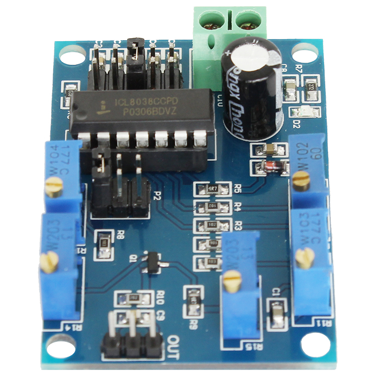
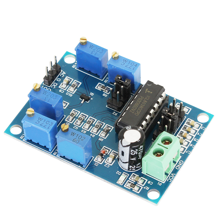
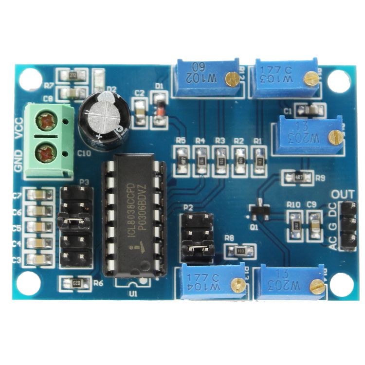
Hardware introduction and description
1.Board size: 54.5*37.8mm
2.Functions of the board
(1)Interface description
VCC,GND: working voltage
AC: with DC bias output
G: ground
DC: pure signal output
(2)Jumper P2 is used for selecting different waveforms(triangular, square or sine waves)
(3)Jumper P3 is used for select different frequency ranges
10Hz-450Hz
90Hz-1.5KHz
940Hz-15KHz
6KHz-120KHz
20KHz-450KHz
(4)Onboard potentiometer’s functions
R11: Frequency adjustment
R12: Square wave duty cycle adjustment
R13: Sine wave linear adjustment
R14: Amplitude adjustment
R15: Square wave linear adjustment
1.Working voltage: 12V ~ 15V
2.Can output triangular wave, square wave and sine wave
3.Frequency range: 10HZ ~ 450kHz
4.Low distortion sine wave: 1%
5.Duty cycle range: 2% to 98%
6.Low temperature drift: 50ppm/℃
7.Triangular wave output linearity: 0.1%
8.Working temperature: 0 ~ 70℃
Hardware introduction and description
1.Board size: 54.5*37.8mm
2.Functions of the board
(1)Interface description
VCC,GND: working voltage
AC: with DC bias output
G: ground
DC: pure signal output
(2)Jumper P2 is used for selecting different waveforms(triangular, square or sine waves)
(3)Jumper P3 is used for select different frequency ranges
10Hz-450Hz
90Hz-1.5KHz
940Hz-15KHz
6KHz-120KHz
20KHz-450KHz
(4)Onboard potentiometer’s functions
R11: Frequency adjustment
R12: Square wave duty cycle adjustment
R13: Sine wave linear adjustment
R14: Amplitude adjustment
R15: Square wave linear adjustment