170W High Power H-bridge Driving Module with Panic Braking
Overview
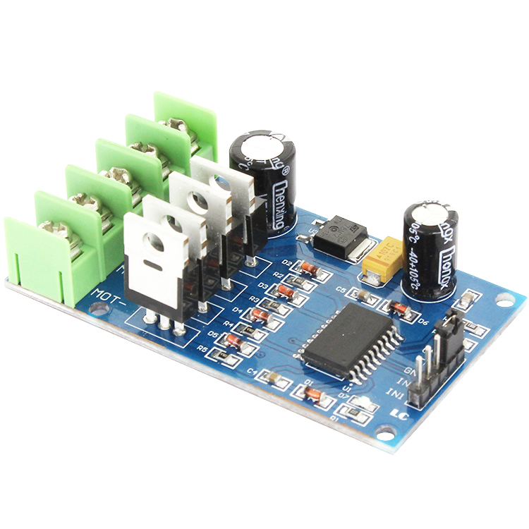
High power H-bridge motor driving module consist of single H-bridge driver IC and 4 external NMOS tube .It has good brake effect with low heat
Function features
High power H-bridge motor driving module consist of single H-bridge driver IC and 4 external NMOS tube .It has good brake effect with low heat
Function features
1.Full bridge drive chip + low pass internal resistance 55V110A NMOS can be used to realize the motor forward and reverse rotation
2.Two-channel PWM input, the duty ratio can be adjusted in 0-100%, with instantaneous braking capacity
3.Working voltage 10V-40V,power below 170W
4.Only three input lines could control the motor,easily and conveniently
5.The chip built-in dead zone hardware control, more suitable for frequent commutation to reduce the pipe loss
6.Support 5V, 3.3V logic input. It is suitable for the direct control of the IO port of different MCU, and it can also control rotation by the analog input
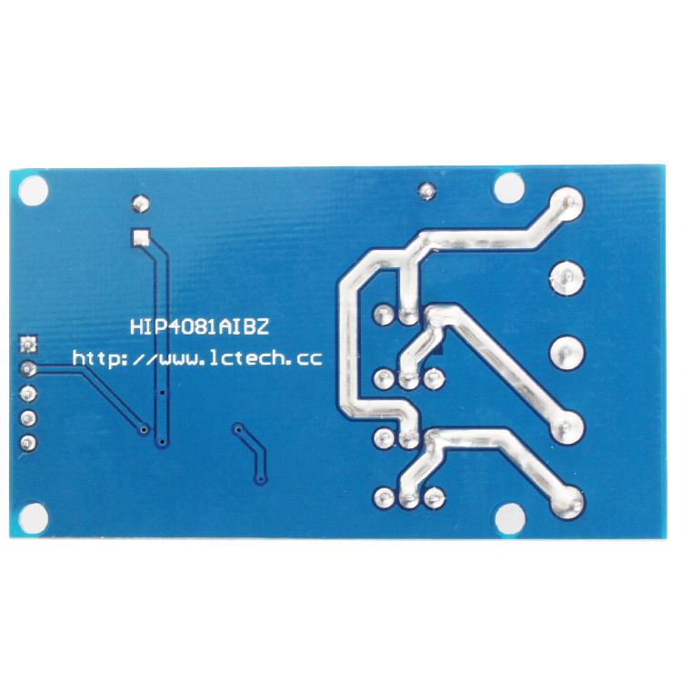
7.The back of the module is tinned for high currency
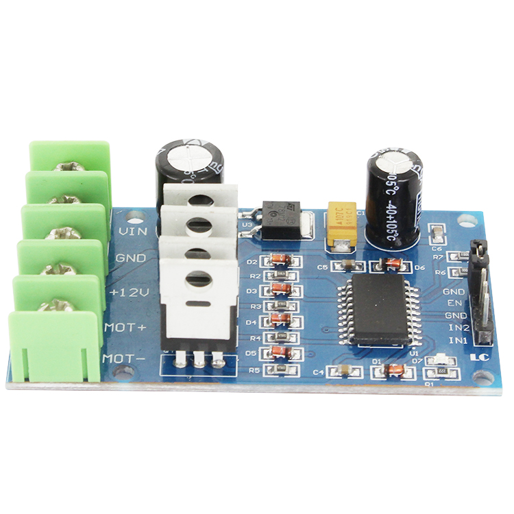
Interface instruction
1.VIN: positive of power supply
2.GND: negative of power supply
3.12V: 12V output
4.MOT+、MOT-: motor output connector
5.EN: enable PIN
6.IN1: logic input 1
7.IN2: logic input 2
User guide
1.Forward and reverse control
IN1 = 1; IN2 = 0; forward rotation
IN1 = 0; IN2 = 1; reverse rotation
IN1 = 0; IN2 = 0; motor brake
2.PWM speed control
IN1 = PWM pulse(0-100%); IN2 = 0; The forward speed is adjustable
IN1 = 0; IN2 = PWM pulse(0-100%); The reverse speed is adjustable
IN1 = 0; IN2 = 0; Motor brake
2.Two-channel PWM input, the duty ratio can be adjusted in 0-100%, with instantaneous braking capacity
3.Working voltage 10V-40V,power below 170W
4.Only three input lines could control the motor,easily and conveniently
5.The chip built-in dead zone hardware control, more suitable for frequent commutation to reduce the pipe loss
6.Support 5V, 3.3V logic input. It is suitable for the direct control of the IO port of different MCU, and it can also control rotation by the analog input
7.The back of the module is tinned for high currency
Interface instruction
1.VIN: positive of power supply
2.GND: negative of power supply
3.12V: 12V output
4.MOT+、MOT-: motor output connector
5.EN: enable PIN
6.IN1: logic input 1
7.IN2: logic input 2
User guide
1.Forward and reverse control
IN1 = 1; IN2 = 0; forward rotation
IN1 = 0; IN2 = 1; reverse rotation
IN1 = 0; IN2 = 0; motor brake
2.PWM speed control
IN1 = PWM pulse(0-100%); IN2 = 0; The forward speed is adjustable
IN1 = 0; IN2 = PWM pulse(0-100%); The reverse speed is adjustable
IN1 = 0; IN2 = 0; Motor brake