L6201 DC Motor Drive Module
Overview
The DC motor drive module is the L6201 chip drive module.L6201 is full control bridge drive chip ,which adopting multi sourcing technology BCD(Bipolar,CMOS,DMOS)to control motor .This chip can integrate independent DMOS field-effect transistors with CMOS and diodes on a single chip.L6201 can realize the optimization of logic circuits and power levels because of modular extension technology.
Function features
1.Working voltage: control signal level 3.3~ 5.5V; Drive motor voltage 7.2~30V
2.Drive DC (7.2~30V voltage motor)
3.Maximum output current 1A
4.The maximum output power is 20W
5.Signal indication
6.Revolving speed is adjustable
7.Strong anti-interference capability
8.Continuous flow protection
9.A DC motor can be controlled separately
10.PWM pulse width and smooth speed adjustment.(The PWM signal can be used to speed the dc motor)
11.It can be reversed
12.This drive is a great time to control the freescale smart car.Small drive pressure drop ,large currency,and strong drive capability
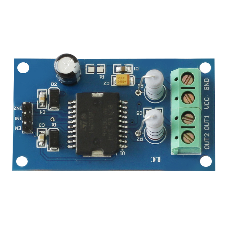
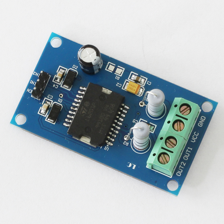
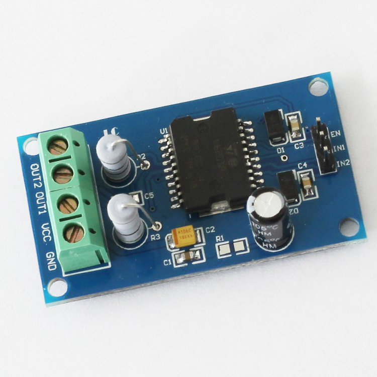
Hardware introduction and description
1.Board size: 29.5*52.2mm
2.Board detailed function
(1)Interface specification
VCC GND is Motor power supply interface
OUT1 OUT2 is DC motor output interface
IN1 IN2 is Motor control interface
EN is Motor enable terminal
Using a drive to control a dc motor.Motor output interface is OUT1 and OUT2. EN port input PWM (Pulse Width Modulation) signal to control motor speed. EN enable PIN could control Hi-low electrical level,high to start and low to stop.It could be controlled by SCM output. Positive and Negative rotation function of motor: signal input terminal IN1 connect Hi-electrical level ,IN2 connect low electrical level for positive rotation.And revise connection for negative.
2.Drive DC (7.2~30V voltage motor)
3.Maximum output current 1A
4.The maximum output power is 20W
5.Signal indication
6.Revolving speed is adjustable
7.Strong anti-interference capability
8.Continuous flow protection
9.A DC motor can be controlled separately
10.PWM pulse width and smooth speed adjustment.(The PWM signal can be used to speed the dc motor)
11.It can be reversed
12.This drive is a great time to control the freescale smart car.Small drive pressure drop ,large currency,and strong drive capability
Hardware introduction and description
1.Board size: 29.5*52.2mm
2.Board detailed function
(1)Interface specification
VCC GND is Motor power supply interface
OUT1 OUT2 is DC motor output interface
IN1 IN2 is Motor control interface
EN is Motor enable terminal
Using a drive to control a dc motor.Motor output interface is OUT1 and OUT2. EN port input PWM (Pulse Width Modulation) signal to control motor speed. EN enable PIN could control Hi-low electrical level,high to start and low to stop.It could be controlled by SCM output. Positive and Negative rotation function of motor: signal input terminal IN1 connect Hi-electrical level ,IN2 connect low electrical level for positive rotation.And revise connection for negative.
| Motor | rotate mode | control end IN1 | control end IN2 | EN capability terminal | |
| M | Positive | High | Low | High |
|
| Negative | Low | High | High |
|
|
| Speed ajustment | * | * | input PWM signal |
|