CH551 CH552 development board core board USB communication 5
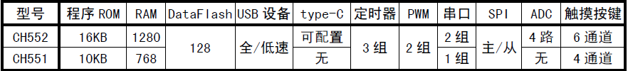
a) About
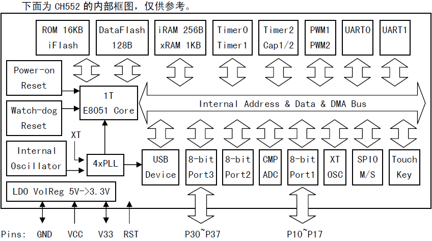
The CH552 chip is an enhanced E8051 core microcontroller compatible with the MCS51 instruction set. 79% of its instructions are single byte single cycle instructions, and the average instruction speed is 8-15 times faster than the standard MCS51CH552 supports a maximum system frequency of 24MHz, with built-in 16K program memory ROM, 256 bytes of internal iRAM, and 1K bytes of on-chip xRAM. xRAM supports DMA direct memory access
CH552 is equipped with ADC analog-to-digital conversion, touch button capacitance detection, 3 sets of timers and signal capture and PWM, dual asynchronous serial port, SPI, USB device controller, and full speed transceiver and other functional modules
CH551 is a simplified version of CH552, with a program memory ROM of 10K and on-chip xRAM of 512 bytes. The asynchronous serial port is only UART0, and the packaging form is only SOP16. The touch buttons have only 4 channels, and the ADC digital to analog conversion module and USB Type-C module have been removed. Everything else is the same as CH552, and you can directly refer to the CH552 manual and materials
b) View
①Front view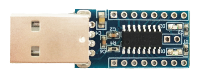
②Side view
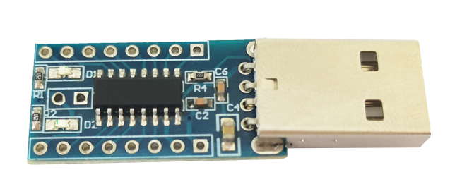
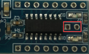
③Reverse image
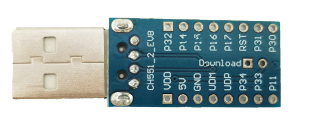
c) Introduction and Explanation
Board size: 49mm * 19.5mm/3g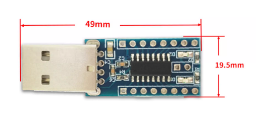
d) Functional Features
Core: Enhanced E8051 core, compatible with MCS51 instruction set, with 79% of instructions being single byte single cycle instructions.The average instruction speed is 8-15 times faster than standard MCS51, with unique XRAM data fast copy instructions and dual DPTR pointersROM: A multi programmable non-volatile memory ROM with a capacity of 6KB, which can be used entirely for program storage spaceor can be divided into a 14KB program storage area and a 2KB boot code BootLoader/ISP program area
DataFlash: A 128 byte non-volatile data storage that can be erased and written multiple times, supporting rewriting data in bytes
RAM: 256 byte internal iRAM, can be used for fast data temporary storage and stack,1KB on-chip xRAM, can be used for large-scale data temporary storage and DMA direct memory access
USB: Embedded USB controller and USB transceiver, supports USB Device device mode, supports USB Type-C master-slave detection,Supports USB 2.0 full speed 12Mbps or low-speed 1.5Mbps, supports maximum 64 byte data packets, built-in FIFO, supports DMA
Timer: 3 sets of timers, T0/T1/T2 are standard MCS51 timers
Capture: Timer T2 has been extended to support 2-channel signal capture
PWM: 2 sets of PWM outputs, PWM1/PWM2 are 2-channel 8-bit PWM outputs
UART: 2 sets of asynchronous serial ports, all supporting higher communication baud rates, UART0 is the standard MCS51 serial port
SPI: The SPI controller has a built-in FIFO, and the clock frequency can reach up to half of the system's main frequency Fsys.,It supports serial data input/output simplex multiplexing and Master/Slave master-slave mode
ADC: 4-channel 8-bit A/D analog-to-digital converter, supporting voltage comparison,Touch Key: 6-channel capacitance detection, supports up to 15 touch buttons, supports independent timed interrupts
GPIO: Supports up to 17 GPIO pins (including XI/XO, RST, and USB signal pins)
Interrupt: Supports 14 sets of interrupt signal sources, including 6 sets of interrupts compatible with standard MCS51 (INT0, T0, INT1, T1, UART0, T2),and 8 sets of extended interrupts (SPI0 TKEY、USB、ADC、UART1、PWMX、GPIO、WDOG), GPIO interrupts can be selected from 7 pins
Watch Dog: 8-bit preset watchdog timer WDOG, supports timed interrupts
Reset: Supports 4 types of reset signal sources, built-in power on reset, software reset and watchdog overflow reset, optional pin external input reset
Clock: Built in 24MHz clock source, can support external crystals by reusing GPIO pins
Power: Built in low voltage difference regulator from 5V to 3.3V, supporting 5V or 3.3V or even 2.8V power supply voltage,Supports low-power sleep, supports USB, UART0, UART1, SPI0 and some GPIO external wake-up
Unique ID number embedded in the chip
e) USB download and usage steps
Taking CH552 as an example1,1. Use a short jump cap or tweezers to short-circuit the following 2 pins and insert the CH552 development board into the computer USB
2. Select chip series: Click on the "8-bit CH55X Series" tab page
3. Select chip model: Select "CH552" from the "Chip Model" list
4. Choose the download method: Select "USB Download" from the "Download Method" list
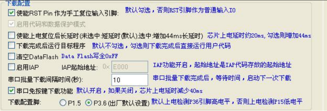
5. Download configuration: Set the download configuration in the "Download Configuration" column
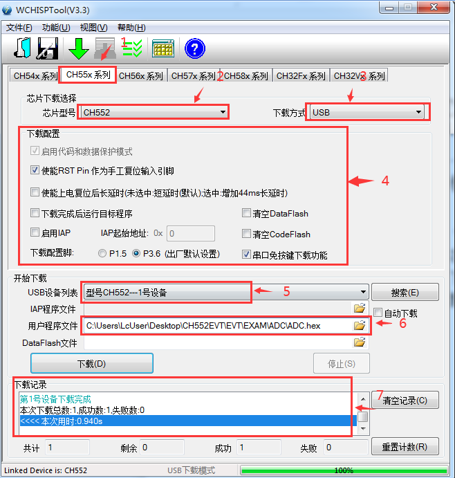
6. Choose the download device: You can select the specified device from the "USB Device List": If the device is connected to a PC, the software will detect it
7. If IAP is not enabled in the download configuration, simply select the corresponding download file for "User Program Files". If IAP is enabled, select the corresponding download files for "IAP Program Files" and "User Program Files", and then click the "Download" button