L298N motor drive module four-way motor drives intelligent c
a) About
The LC four channel L298N motor drive module integrates two L298N chips and can drive four DC motors simultaneously,achieving control over forward and reverse rotation as well as motor speed.
The module is equipped with an LM2596S voltage reducing chip,
which can output 5V power to the control terminal when driving motors with a voltage of 7V or higher
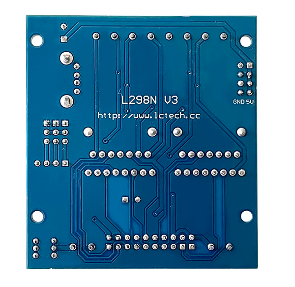
b) View
①Front view
②Reverse image
c) Functional Features
1. Peak driving current IO: 2A2. Maximum power consumption: 50W (when T=75 ℃, a single L298N 25W)
3. The power supply range of the logic terminal is VSS:+5V to+7V (can be powered from the board+5V)
4. Operating current range of logic part: 0-36mA
5. Control signal input voltage range: Low level:-0.3V≤Vin≤1.5V(control signal invalid), High level:2.3V≤Vin ≤VSS(control signal valid)
6. Onboard multi-channel 5V power output port
d) Introduction and Explanation
Board size: 59.1mm * 64mm /55g
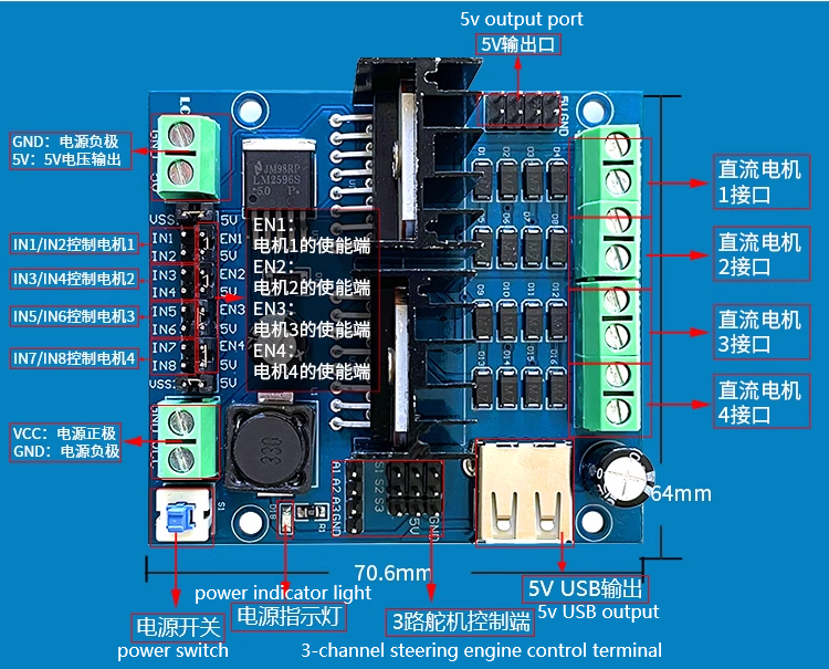
Board Function Description:
1. Interface Description:VCC: Positive pole of power supply
GND: Negative pole of power supply
OUT1, OUT2: DC motor 1 interface
OUT3, OUT4: DC motor 2 interface
OUT5, OUT6: DC motor 3 interfaces
OUT7, OUT8: DC motor 4 interfaces
IN1-IN8: Motor logic control terminal
IN1/IN2 controls motor 1
IN3/IN4 control motor 2
IN5/IN6 control motor 3
IN7/IN8 control motor 4
EN1: Enable end of motor 1
EN2: Enable end of motor 2
EN3: Enable end of motor 3
EN4: Enable end of motor 4
S1: Power switch
5V: 5V voltage output
e) L298N 4-channel motor drive board
Introduction to pins and parameters:Pin Overview

Performance Parameters
| Working mode | H-bridge driver (4 channels) | Main control chip | 2 dual H-bridge L298N chips |
|
Drive voltage VSS1 and VSS2 (default 5V) |
5-30V | Power chip | LM2596-5.0 switching power supply, superior to LM7805 |
| Logic voltage | 5V | Logic current | 0-36mA |
| Supply voltage VCC (recommended value) | 7-12V | Supply voltage VCC (limit value) | 6-30V |
| Single bridge maximum driving current | 2A | maximum total power consumption | 20W |
f ) Instructions for use
(1) L298N, as the main driver chip, has the characteristics of strong driving ability, low heat generation, and strong anti-interference ability. At the same time, the LM2596 switching power IC installed also maximizes power efficiency, lower power consumption, and stronger power(2) Connecting the servo: The board carries three servo interfaces, each containing three pins: S, 5V, and GND. If the servo under ultrasound in this experiment is plugged into the first circuit, the yellow, red, and brown wires of the SG90 servo correspond to S1, 5V, and GND, respectively. The PWM signal for controlling the servo is input from pin A1 on the side, and the remaining servo interfaces can be used to power external 5V devices
(3) Connect VCC and GND to 18650 battery during use; IN1-IN8 are connected to the high and low levels output by Arduino to control the forward, reverse, and stop of the motor< EN1-EN4 are enable/speed control pins, and the speed can be adjusted by using a microcontroller to output PWM with variable duty cycle. If speed control is not required, jumper caps can be used to connect them to 5V on the L298N module (at full speed operation)
The following is the control logic for IN1-IN8 when controlling DC motors:
| DC motor | rotation mode | IN1 | IN2 | IN3 | IN4 | IN5 | IN6 | IN7 | IN8 |
| M1 | Forward rotation | High | Low | ||||||
| M1 | Reverse | Low | High | ||||||
| M1 | Stop | Low | Low | ||||||
| M2 | Forward Rotation | High | Low | ||||||
| M2 | Reverse | Low | High | ||||||
| M2 | Stop | Low | Low | ||||||
| M3 | Forward Rotation | High | Low | ||||||
| M3 | Reverse | Low | High | ||||||
| M3 | Stop | Low | Low | ||||||
| M4 | Forward Rotation | High | Low | ||||||
| M4 | Reverse | Low | High | ||||||
| M4 | Stop | Low | Low |
Note: If the program and the wiring of IN1-IN8 are correct but the direction of a certain motor is reversed, such as motor M1, then swapping the two wires OUT1 and OUT2 can be done