USB to Ethernet USB to Ethernet Serial Transparent Communica
a) About
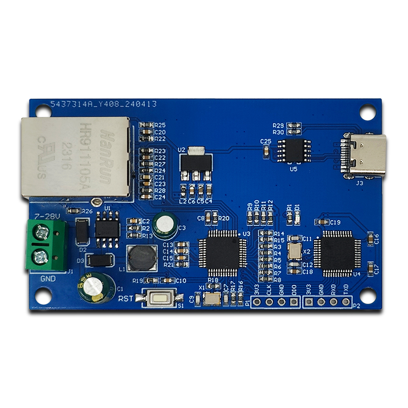
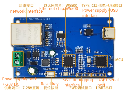
The LC USB to Ethernet module uses STM32F103C6T6 as the main control chip, equipped with CH340K to achieve USB to TTL conversion, and uses W5500 Ethernet chip; This module can serve as a TCP server, which can be connected to a computer using a USB cable and an Ethernet cable to enable data exchange between the USB interface and the TCP server; This product supports DC7-28V power supply and Type_C port power supply.
b) View
①Front view
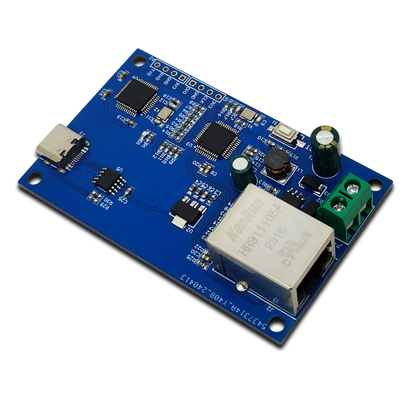
②Side view
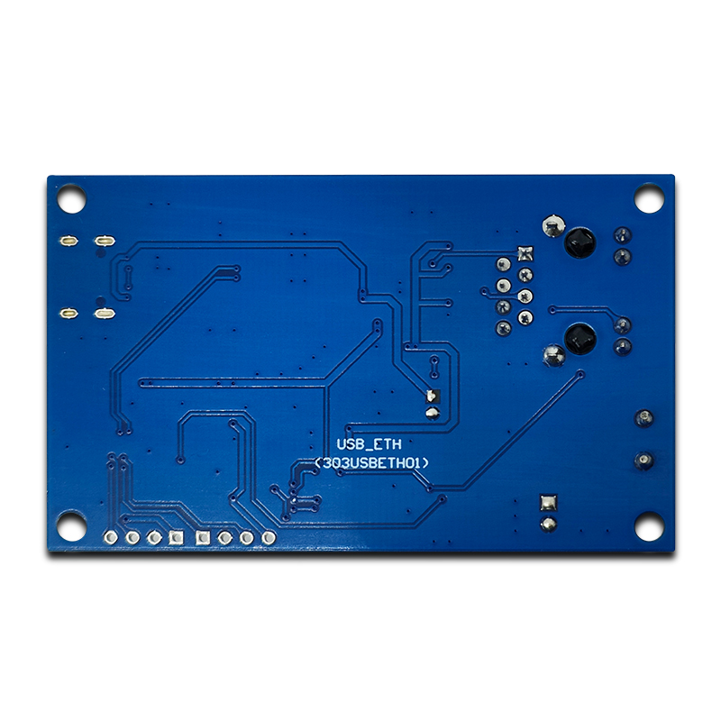
③Reverse image
c) Introduction and Explanation
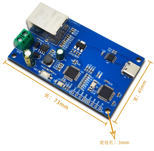
Size: 45 * 73mm/21 g (positioning hole: 3mm)
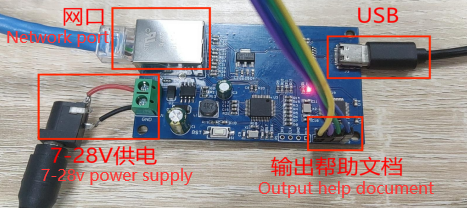
Interface Introduction
d) Functional Features
. On board mature and stable STM32F103 series 32-bit microcontroller;
. The module IP address and port number are fixed and do not require configuration;
. Supports Type_C port power supply and DC7-28V to 5V power supply circuit power supply;
. Reserved UART serial port and SWD debugging port, supporting secondary development;
e) Module usage instructions
1. Program burning - USRT: Prepare a USB to TTL module (such as CH340) and plug it into the computer's USB port. The connection method to the module is as follows:
| TTL Serial port module | USB to Ethernet module |
| GND | GND |
| TX | RX |
| RX | TX |
| 3.3V | 3.3V |
Then short-circuit the BOOT0 pin to 3.3V to burn the firmware;
2. Program burning - SWD: Prepare a Link debugger (ST Link, J-Link, etc.) and plug it into the USB port of the computer. The Link and module connection method is as follows:
| Link debugger | USB to Ethernet module |
| GND | GND |
| SWCLK | SWCLK |
| SWDIO | SWDIO |
| 3.3V | 3.3V |
Then select the firmware for burning;
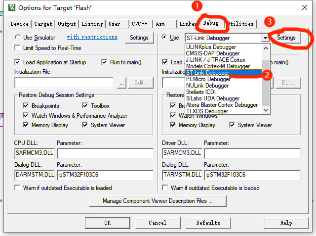
3.Debug: After connecting the Link burner in the above way, click the "Debug" button of the compiled software, select "ST Link", and then click Settings;
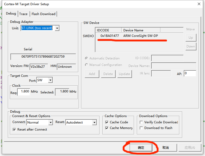
If the SW Device displays a device, it means that the debugger has successfully recognized it. Set the parameters according to the following figure and click OK.
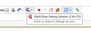
Then press Ctrl+F5 or click the debug button to start debugging:
4. Module function testing
Connect the module as shown in the following figure and open the "serial debugger" software:
USB interface: After opening the serial port debugger, select the corresponding port and choose "9600" bit rate, then click to open the serial port. If the network connection is successful, it will return a "ready" message, and you can start sending data to the server (RJ45 network port);
RJ45 Ethernet port: After opening the serial debugger, select the port number "TCPClient", enter "192.168.0.72:5000" in the remote box, click on the connection, and the bottom will display that the connection is successful. After that, you can send data to the USB interface;
UART interface: After power on, it will output help documents, display product information and network connection status.
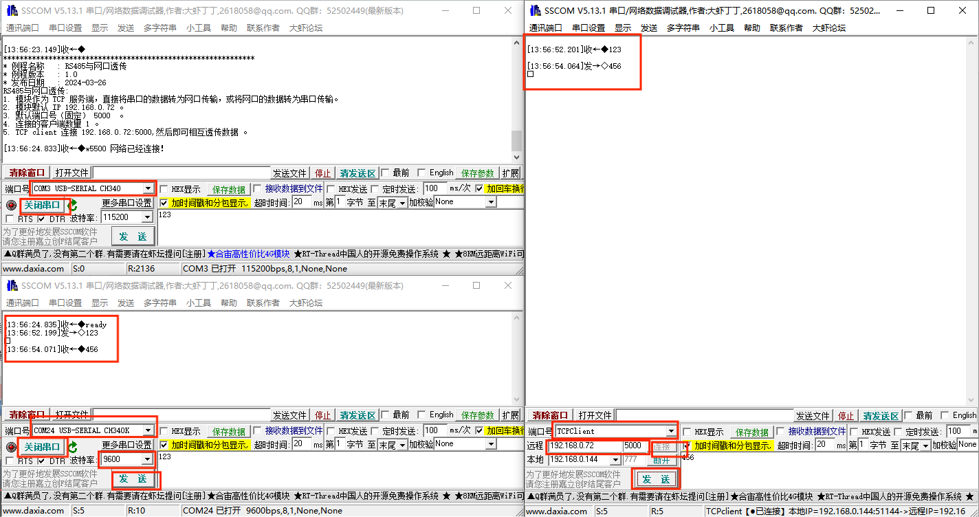
The above test shows that the data transmission is normal.
f) Download User Manual
For more product information, please refer to [Baidu Netdisk]extraction code: srqk