AC+DC power supply WB2-12F single relay module development b
a) About
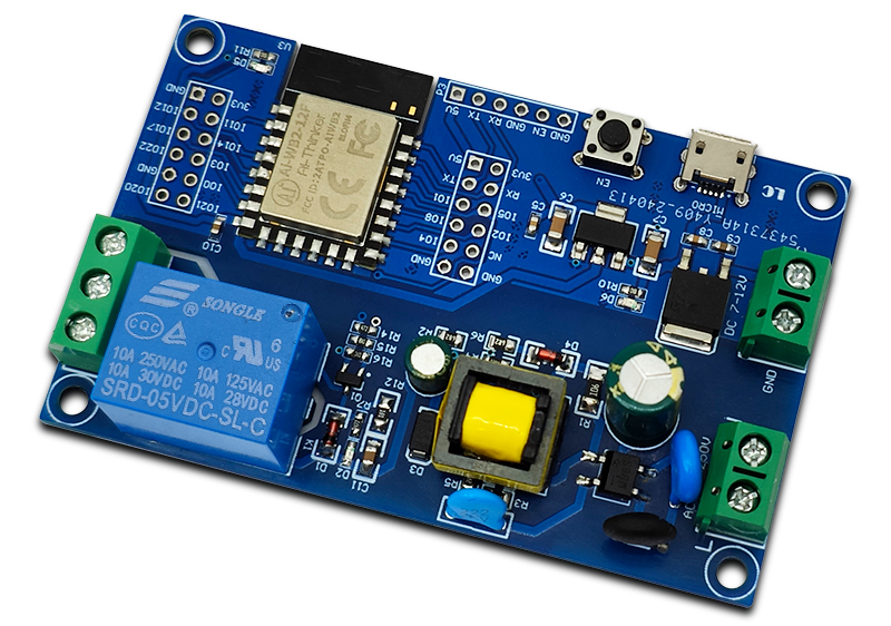
The LC AC+DC powered WB2-12F single relay module is equipped with the Ai-WB2-12F module, with all I/O ports leading out, onboard EN enabled keys and programmable LED indicator lights, supporting AC90-250V power supply+DC7-28V power supply. Suitable for WB2 secondary development learning, smart home wireless control and other occasions.b) View
①Front view

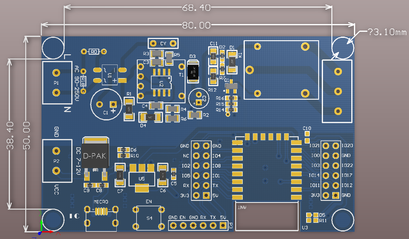
②Side view
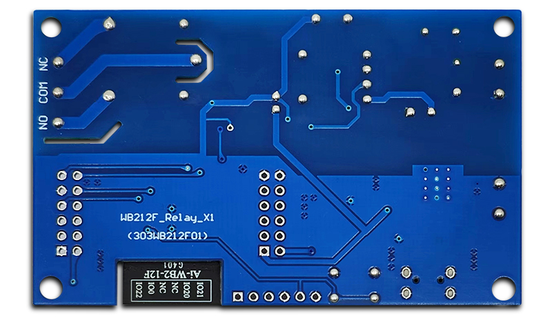
③Reverse image
c) Functional Features
1. Onboard the new series of Ai-WB2-12F modules with a large capacity of 4M Byte Flash;
2. All I/O ports and UART program download ports of the WB2-12F module are exported for easy secondary development;
3. Onboard AC-DC power module, supporting AC90-250V power supply mode, onboard DC-DC power module, supporting DC7-28V power supply mode.
4. Onboard EN enable buttons and programmable LED indicator lights;
5. WB2-12F supports the use of BLDevCube burning tool and provides factory firmware;
6. Onboard single channel 5V relay, output switch signal, suitable for controlling loads with operating voltage below AC 250V/DC30V;
d) Introduction and Explanation
Size: 50 * 80mm/34 g (positioning hole: 3mm)
Interface Introduction
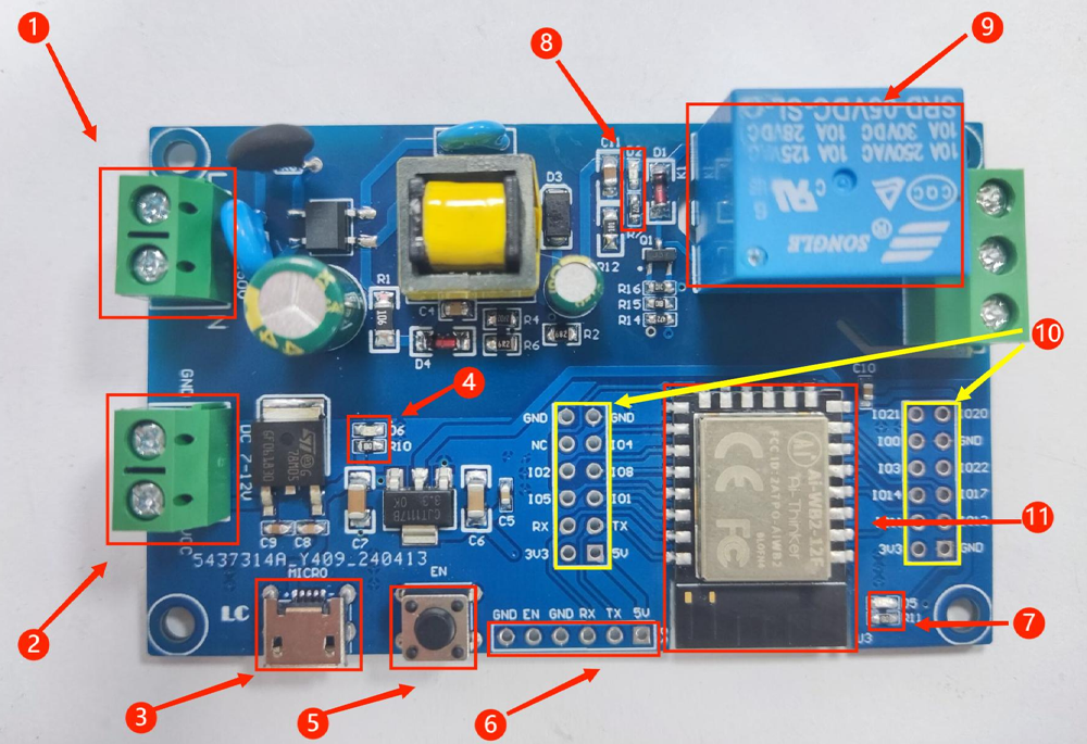
1. AC power supply port: 90-250V AC power
2. DC power supply port: 7-28V DC power
3. Micro-USB power supply port
4. Power indicator light
5. EN button: default as chip enable, high level effective
6. UART program burning port
7. Programmable LED indicator light (IO12 pin control)
8. Relay indicator light
9. Single channel 5V relay
10. All IO pins
11.MCU:Ai-WB2-12F(SMD)
Module testing
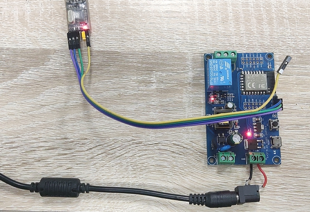
1. Power on the module and prepare a USB to TTL serial port module to plug into the computer USB. The connection method between the serial port module and the development board is as follows:
| TTL Serial port module | WB2-12FD evelopment board |
| GND | GND |
| TX | RX |
| RX | TX |
2. Open the SSCOM serial port data debugger, select the correct port and baud rate, click "Open Serial Port", and prepare to send AT commands;
3. Send "AT" and return an "OK"; Then send 'AT+SYSIOMAP?' to query the IO pin mapping relationship table of the development board:
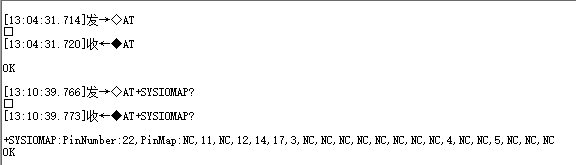
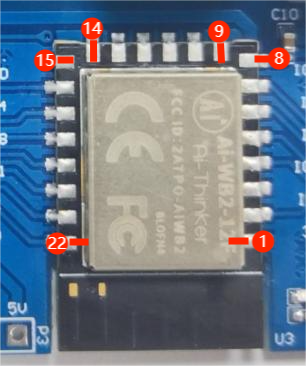
The order of all pins is sorted counterclockwise from the top left corner of the module, with pin numbers starting from 1 and corresponding chip pin numbers 1-22. If the module does not have a corresponding chip pin, it is set to NC, as shown in the following figure:
4,The relay is controlled by the IO5 pin to control the switch state. Here, setting the IO5 pin (i.e. pin 19) to a high level will turn on the relay. Sending "AT+SYSGPORITE=19,1" will turn on the relay and its indicator light; Send 'AT+SYSGPOWRITE=19.0', and the relay and relay indicator light will turn off:
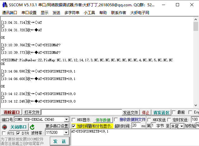
The above module testing process is normal
*For more AT instruction sets and examples, please refer to the official website of Ai-Thinker:
https://aithinker-combo-guide.readthedocs.io/en/latest/index.html
Firmware development and burning methods
1. Ai-WB2 series module secondary development SDK source code address:https://github.com/Ai-Thinker-Open/Ai-Thinker-WB2
2. Ai-WB2 series module secondary development Linux development environment setup:https://aithinker.blog.csdn.net/article/details/125604649
3.Ai-WB2 series module secondary development, Windows development environment setup:https://blog.csdn.net/Boantong_/article/details/128480919
4.Ai-WB2 series module secondary development programming guide:https://wb2-api-web.readthedocs.io/en/latest/docs/api-guides/index.html
5. Ai-WB2 series module firmware burning guide:https://aithinker.blog.csdn.net/article/details/125781602
6.Ai-WB2 series module secondary development firmware burning software download:https://docs.ai-thinker.com/_media/bl602_flash_download_tool.zip
7. Video tutorial on secondary development of Ai-WB2 series modules and setting up a Windows development environment:https://www.bilibili.com/video/BV1Rd4y117oA/
8. Ai-WB2 series module firmware burning video:https://www.bilibili.com/video/BV1xd4y1C74q/
9. For other details, please refer to the official website of Ai-Thinker:https://docs.ai-thinker.com/wb2
e) Application scenarios
The LC applicable scenarios for the AC+DC powered WB2-12F single relay module include:
Smart Home: Control smart devices in the home, such as lighting, curtains, air conditioning, etc., to achieve remote control and automation.
Industrial automation: In industrial control systems, controlling the start and stop of mechanical equipment to improve production efficiency.
Building automation: integrated into intelligent building management systems to control elevators, lighting, safety systems, and more.
Education and Research: As a teaching tool, it helps students and researchers learn embedded systems and IoT technology.
Wireless control devices: used for developing and controlling various wireless control devices, such as smart sockets and wireless switches.
Medical equipment management: Control the switch of medical equipment, suitable for equipment management in hospitals or clinics.
Agricultural monitoring: Control agricultural equipment, such as irrigation systems, to achieve precision agriculture.
Security system: used for security monitoring, controlling the opening and closing of devices such as cameras and alarms.
Emergency response system: As a control unit for emergency stop buttons or safety systems, it enhances safety.
Energy management: Control energy consuming equipment, optimize energy use, suitable for smart grids or solar energy systems.
f) Download User Manual
For more product information, please refer to [Baidu Netdisk]extraction code: cf98