0.96 inch OLED display module with button EC11 rotary encode
a) About
The LC rotary encoder button OLED display module is equipped with a 0.96-inch 128x64 pixel OLED screen and EC11 rotary encoder and one touch button. It communicates with the outside world through the IIC communication interface and button interface. The module has the characteristics of small size, fast response, and stable performance.
b) View
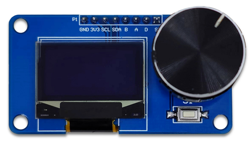
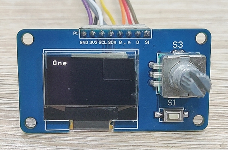
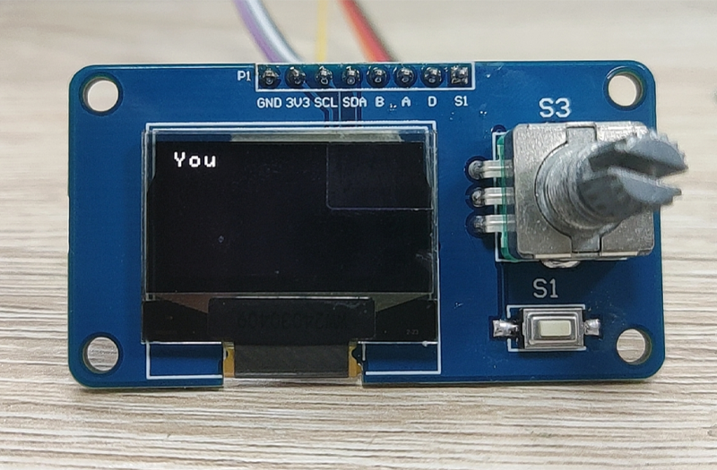
①Front view
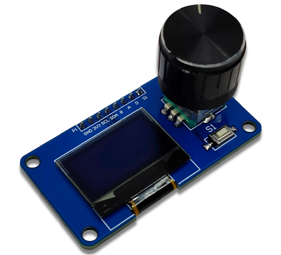
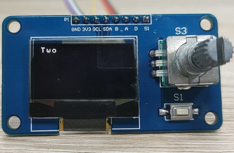
②Side view
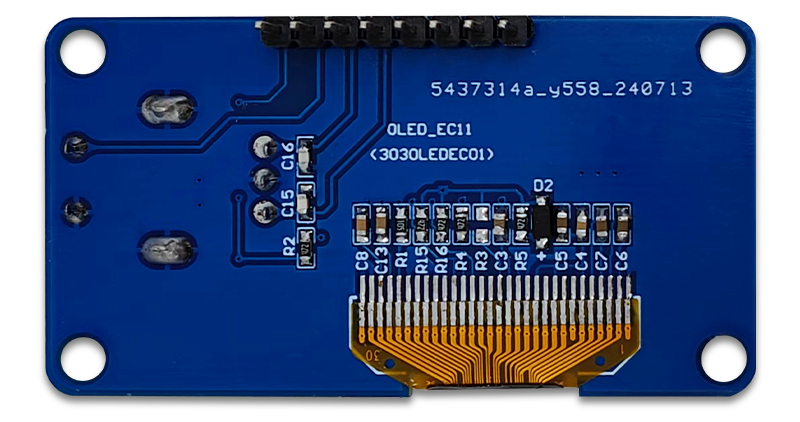
③Reverse image
c) Functional Features
1. Equipped with a 0.96-inch OLED screen and an IIC communication interface;
2. Onboard EC11 rotary encoder+1 touch button, and lead out interface;
3. Connect external microcontrollers through pins for use;
4. It has the characteristics of small size, fast response, and stable performance;
d) Introduction and Explanation
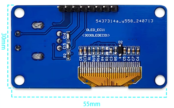
Board size:30*55mm/14 g
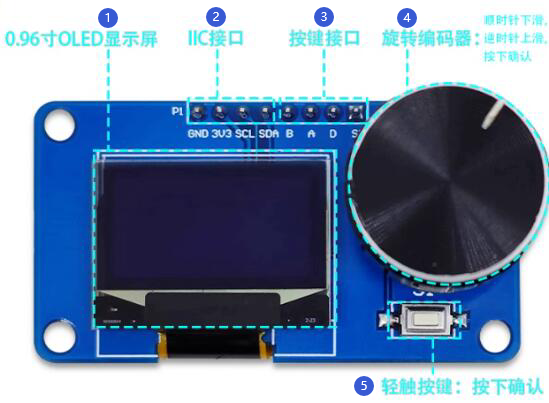
① 0.96-inch OLED display screen
② IIC interface
③ Key interface
④ Rotary encoder:Clockwise descent,Slide counterclockwise upwards,Press confirm
⑤ Tap the button: Press to confirm
e) Minimum Development Board Burning Instructions
1. Program burning - USRT: Prepare a USB to TTL module (such as CH340) to plug into the computer's USB port, and then prepare an STM32 mini development board. The connection method is as follows:
| TTL serial port module | STM32 Minimum Development Board |
| GND | GND |
| TX | RX |
| RX | TX |
| 3.3V | 3.3V |
Then plug in the jumper cap between the BOOT0 pin and 3.3V to burn the firmware;
2. Program burning - SWD: Prepare a Link debugger (ST Link, J-Link, etc.) to plug into the USB port of the computer, and then prepare an STM32 mini development board. The connection method between Link and the development board is as follows:
| Link debugger | STM32 Minimum Development Board |
| GND | GND |
| SWCLK | CLK |
| SWDIO | DIO |
| 3.3V | 3.3V |
Then select the firmware for burning;
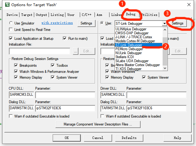
Debug: After connecting the Link burner in the above way, click the "Debug" button of the compiled software, select "ST Link", and then click Settings;
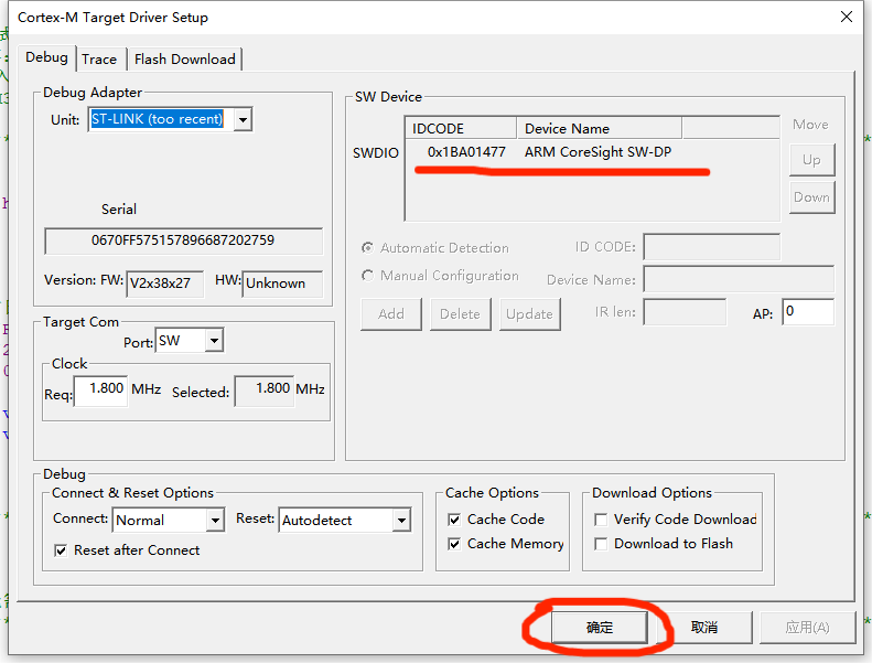
If the SW Device displays a device, it means that the debugger has successfully recognized it. Set the parameters according to the following figure and click OK.
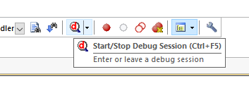
Then press Ctrl+F5 or click the debug button to start debugging:
3. Module function testing
After the burning is completed, connect the OLED display module to the minimum development board according to the following table:
| Display module | STM32 Minimum Development Board |
| GND | GND |
| 3.3V | 3.3V |
| SCL | PA5 |
| SDA | PA7 |
| B | PA1 |
| A | PA2 |
| D | PA3 |
| S1 | PA4 |
Then power on, as shown in the figure:
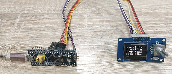
After booting up, the screen will display the initial menu;
Rotate the encoder clockwise or counterclockwise, and the cursor will slide up and down. Then press S1 or press the encoder, and the screen will enter the secondary menu. Turning the knob again will exit:
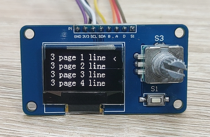
The above tests show that everything is normal on the module.