5V ESP8266 WiFi Relay IoT smart home Cellp hone APP teleswit
Date:2020-07-17 Views:
Technical info: https://www.mediafire.com/file/0wo1fs8l2w7n0qy/New_ESP8266_1-Road_WIFI_Relay.zip/file
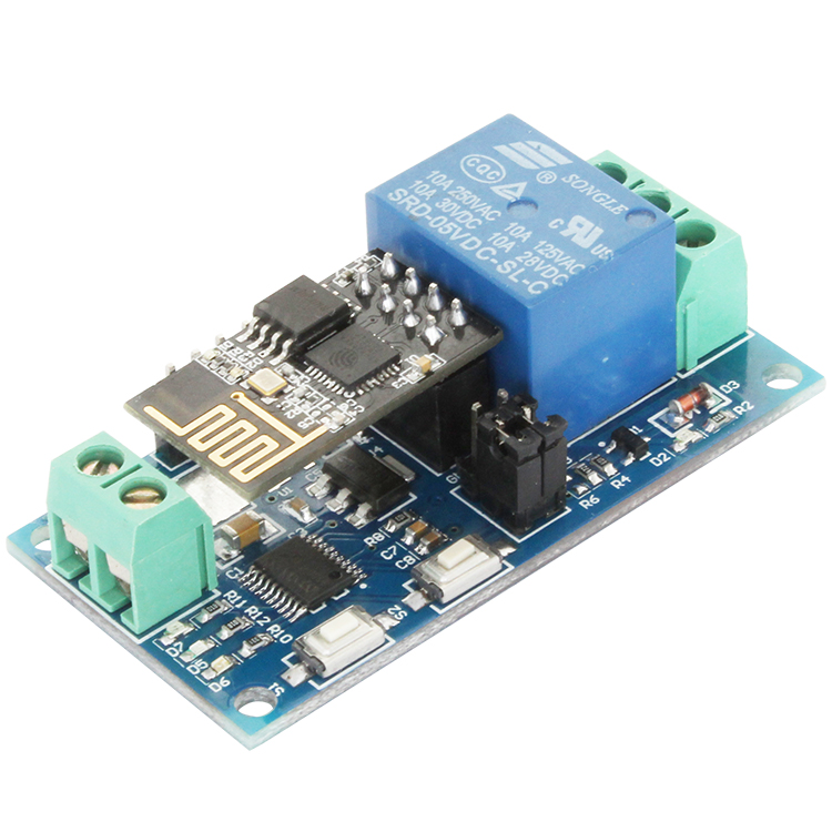
LC5V ESP8266 single-channel WIFI relay module equip with to ESP-01 WIFI module and STM8S high performance MCU, Only need simple configurations and then you can control the relay with cellphone APP under LAN area.
1. The function and characteristics
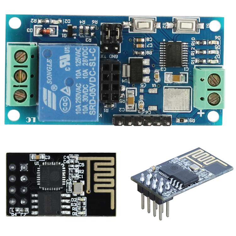
1, On-board STM8S003 and ESP-01 WIFI module
2, Having two modes:
(1) Mode 1: Cell phones carry on the wifi module directly
(2) Mode 2: Cell phone and wifi module carry on the same router
Additional function: As an USB relay module when unplug the ESP-01
3, Transmission distance:
(1) In the open environment, the maximum transmission distance is 100m when the cell phone carry on the wifi module directly ;
(2) when the wifi module and cell phone carrying on the same router ,the transmission distance depend on the router’s signal intensity;
4, Use Smartconfig technology of ESP8266 to configurate the password for the ESP-01 module with APP
5, On-board 5V, 10 A / 250 v AC 10 A / 30 v DC relay, absorb 100000 times continuously, Module with diode effusion protection, short response time
6, On-board model selection and working position indicator LED
7, On-board preserved UART debug interface and STM8 SWIM interface
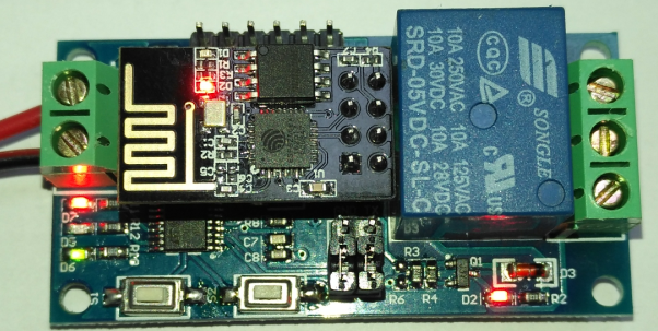
2. Introduced the hardware and instructions
Size:57.4*29mm
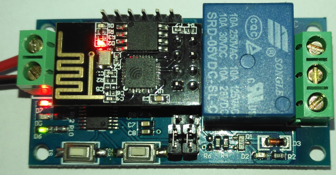
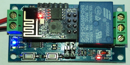
The board function description:
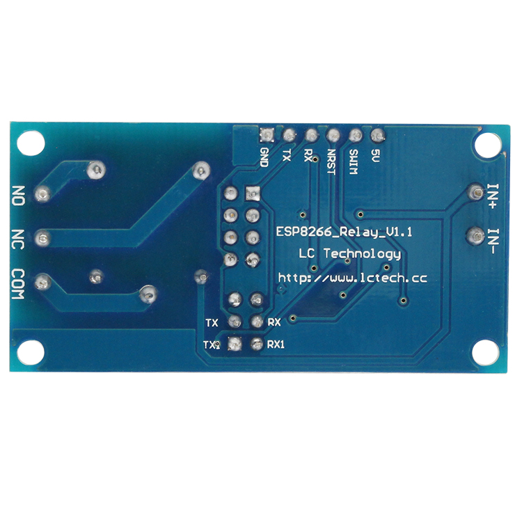
1,Interface and sources:
IN+、IN-:5Vpower input
TX、RX:UART communication
SWIM、NRST:STM8S SWIM interface
S1:Mode selection key,default is mode 1
S2:Restore key
LED D2(red): Relay indicator
LED D7(red): Mode 1 indicator
LED D5(blue):Mode 2 indicator
LED D6(green):Working state indicator,the description of D6 as below:
(1)It’s means internal self-configuration or lost connection with the router when D6 off
(2)It’s means the ESP-01 are waiting for the APP configurate the password for it when D6 fast blink every 0.5S
(3)It’s means the whole configuration is done and waiting for establishing TCP connection with APP when D6 slow blink every 2S
(4) It’s means the TCP connection between ESP-01 and APP is OK when D6 on all the time 。
Relay control command(must be hex format):
Open the relay: A0 01 01 A2
Close the Relay:A0 01 00 A1
2,Preparatory work:
(1)5V DC adapter, connect to IN+ and IN-
(2)Installing APP “EspTouch_Demo” on your Android phone,it is used for configurate password for ESP-01 when the first time you use working mode 2
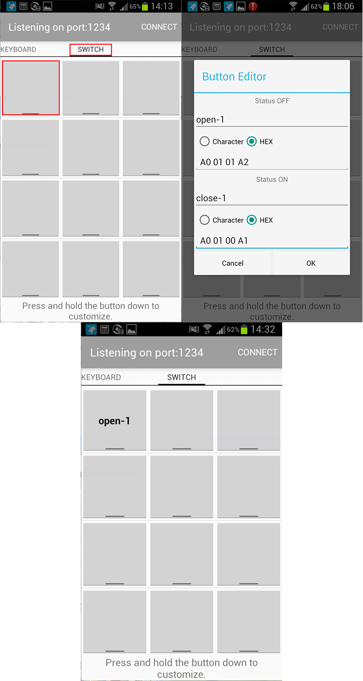
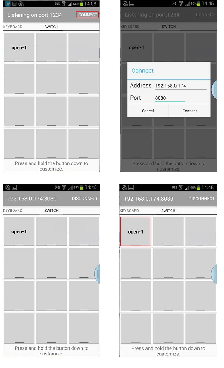
(3)Installing APP “EasyTCP_20” on your Android phone,this is a TCP communication tool,and used for send the relay command to the ESP-01 with your phone. Click”SWITCH” , press the function block and insert the relay command name and content(Remark: the command content is HEX format)
3, Working mode 1: (Cell phones carry on the wifi module directly) instructions:
(1)Plug the ESP-01 module, turn on the power, wait about 4 seconds,the status of D6(green) will change to slow blink every 2S,it means the configuration is done,as blow:
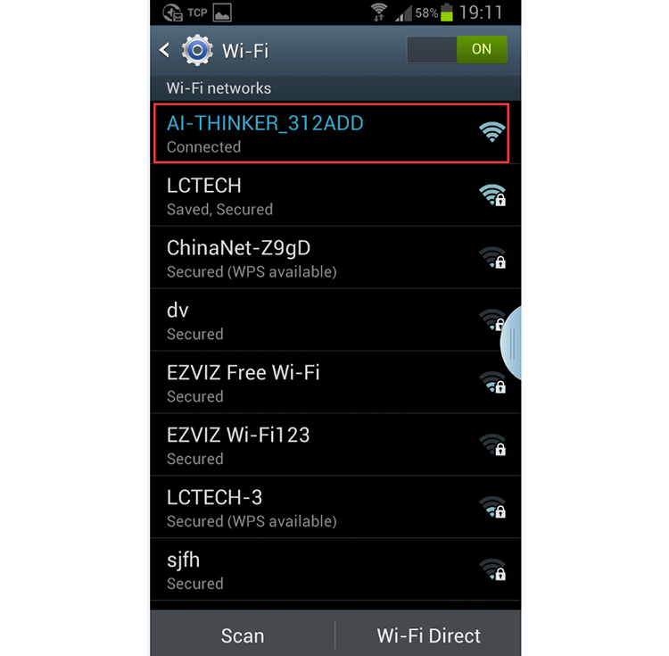
(2) Connecting to the AP signal that generated by ESP-01 with your phone
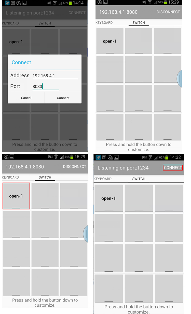
(3)Open the “EasyTCP_20”APP, click”CONNECT”, insert IP address and port number, click “Connect” , and then you can click the function block to control the relay after the status of D6(green) is on all the time.
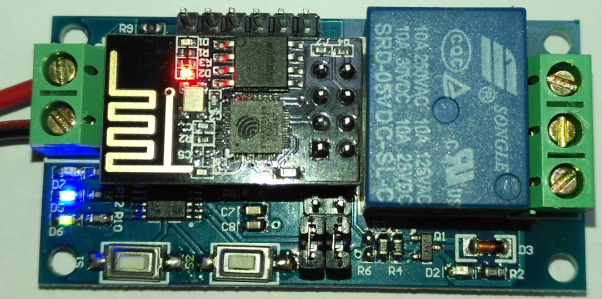
4, Working mode 2: (Cell phone and wifi module carry on the same router) instructions:
(1)Plug the ESP-01 module, turn on the power, wait about 4 seconds,the status of D6 will change to slow blink every 2S, and press the S1 to switch the working mode to mode 2, the blue LED will on. Please wait about 20S, the green LED change to 0.5S fast blink, it’s mean you need configurate password for the ESP-01:
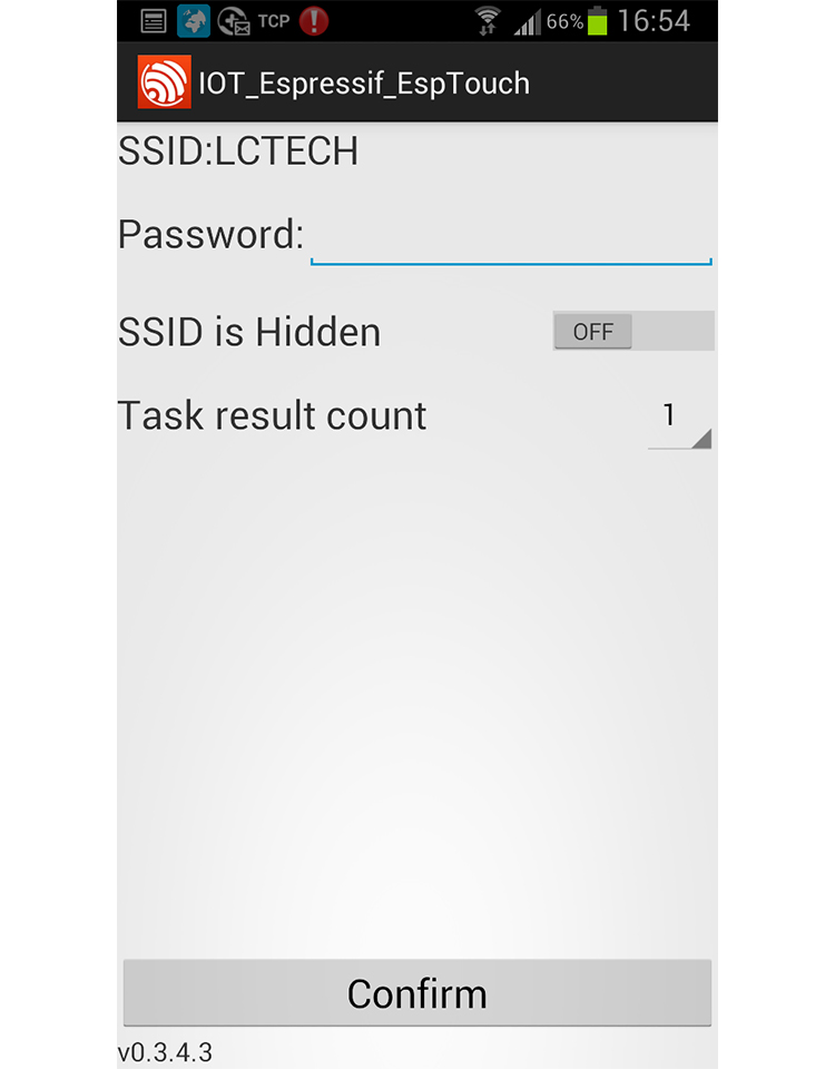
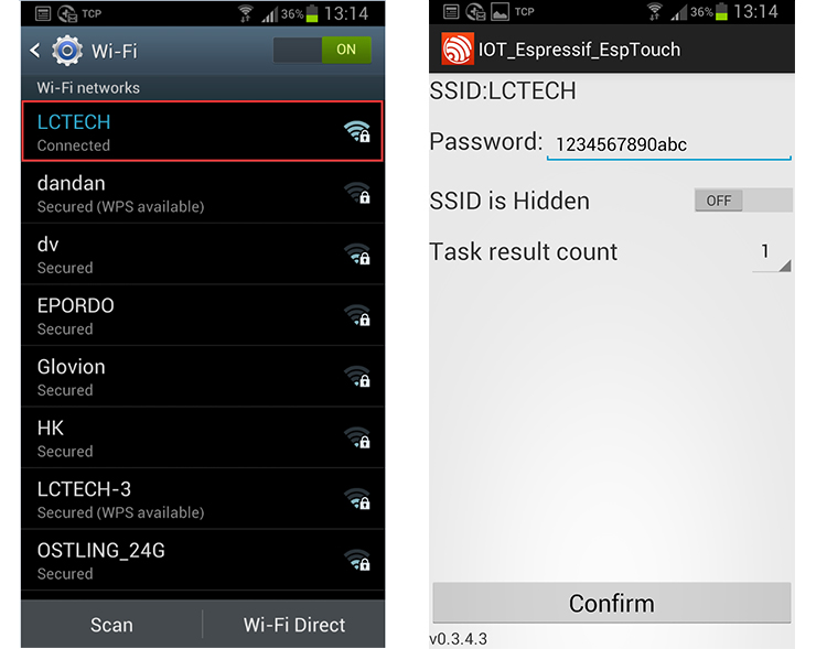
(2) Connect to the router with your phone, open “EspTouch_Demo”APP, insert the password of the router, click”Confirm”
(3) Waiting for the configuration success, it’s means the ESP-01 connect to the router successfully when you see IP address on screen(such as 192.168.0.174). After that, the ESP-01 will remember this password, it will try to connect to this router automatically when the next time you enter the working mode 2(about takes 20-60S)
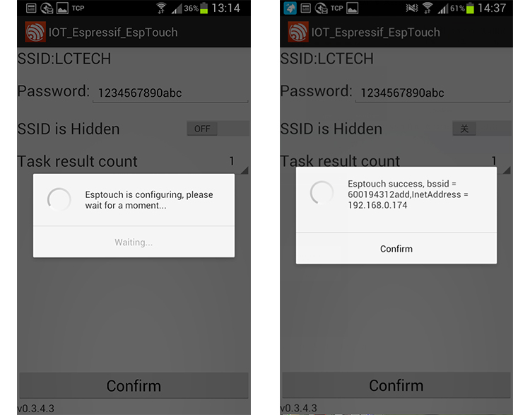
Note: The ESP-01 IP address 192.168.0.174 is allocated by the router, maybe it will change when you restart the wifi relay module, so you can check the real time IP address of ESP-01 on your router device list
(4) Open “EasyTCP_20”APP, click “CONNECT”. Input IP address and port number of the ESP-01, click “Connect”, and then you can click the function block to control the relay after the status of D6(green) is on all the time.
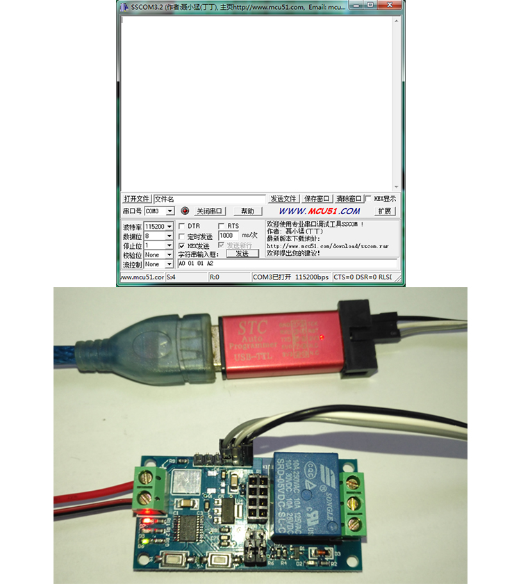
5, Additional function
(As an USB relay module when unplug the ESP-01)instructions:
For that,You need an USB to TTL module, and the GND,TX,RX pins of the TTL module connect to the GND,TX,RX pins of the wifi relay module.Unplug the ESP-01 module, turn on the power, wait about 4 seconds,the status of D6(green) will change to slow blink every 2S. Open a Serial debugging software on your PC, the baud rate is 115200.After that you can send command A0 01 01 A2 to open the relay,and A0 01 00 A1 to close the relay(remark: the command format is HEX),just as show below:
Kindly Remind:
1, For working mode 2, you only need configurate password for the ESP-01 at the first time, after the ESP-01 connect to the router successfully, it will save this password and connect to the router automatically when you enter the working mode 2 at next time
2, If you want to change the router, you can press the S2(this key will clear the saved password), and then you can configurate the new password for the ESP-01 again.
3, The status LED(D6) will off and try to connect to the router again when the ESP-01 lost connection with the router. During this period, the key(S1 and S2) are not available. It’s means the connection is recovered when D6 slow blink every 2S.
4, The key(S1 and S2) are available only when the LED(D6) slow blink every 2S or on all the time, it’s means the wifi relay module are doing self-configuration or waiting for the configuration that from your phone under other conditions
5, The ESP-01 module have timeout mechanism, it will kick off your phone and disconnect TCP relationship when no data transmit exceed 6 minutes. For this conditions, you can click the “CONNECT” on “EasyTCP_20”APP interface and establish connection with ESP-01 again.