Integrity - based innovation in science and technology Home|Favorite|Contact us
Name:Helen.
Tel:+86-755-82720811
E-mail:helen@chinalctech.com
Add:Room 301,Building No.3,Guole Technopark,Lirong Road,Dalang Street,Longhua District,Shenzhen 518110,China.
Online consultingSKU: LC-ESP12-CLK-096
Overview
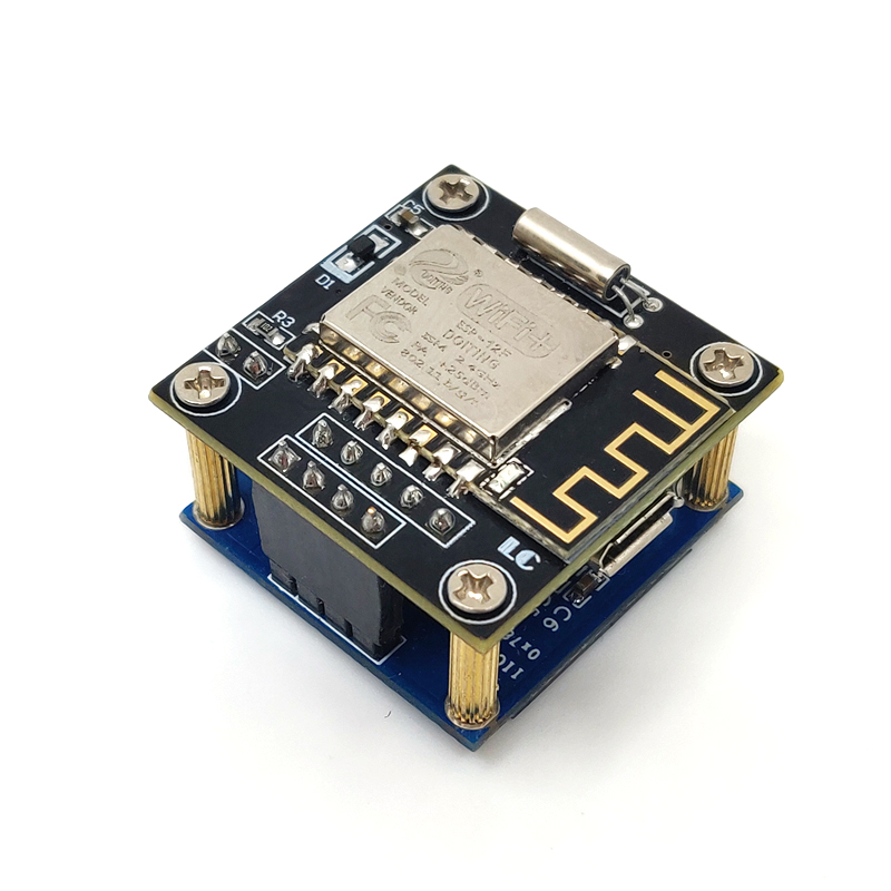
LC ESP8266 0.96 inch OLED Clock module integrated ESP-12F module ,0.96inch OLED display 、RTC Perpetual calendar clock chip and CR1220 battery, provide matching configuration software, Can be used for DIY own LCD WiFi clock . Lead to the ESP8266 programming port, if you are interesting this product you can make it secondary development .
Function features
1.Onboard mature and stable ESP-12F WiFi module, high capacity 4M Byte Flash
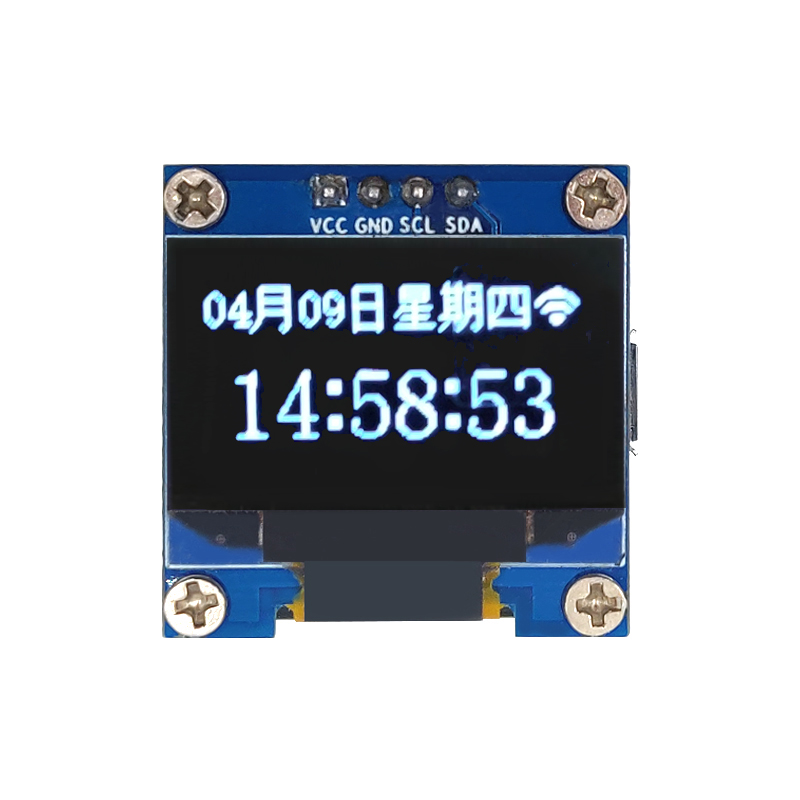
2.Onboard 12C communication Interface 0.96-inch OLED display
3.Provide reference codes and documents in environments such as OLED display 51 and STM32
4.Onboard PCF8563T clock circuit,even if disconnect power, also can working normally
5.Reserved ESP8266 UART interface ,support secondary development and program yourself hardware
6.Provide ESP8266 factory firmware, schematic
7.Power supply: Micro USB 5V power supply
8.Double layer structure design, small size and good appearance, DIY WiFi clock best choice
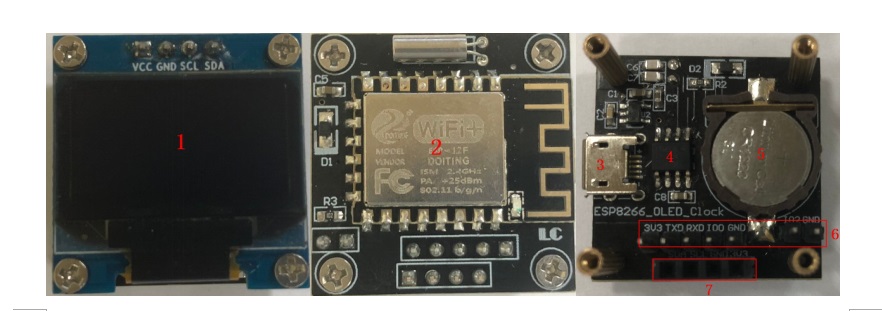
Hardware introduction and description
1.Board size: 29*29mm; Weight: 13g
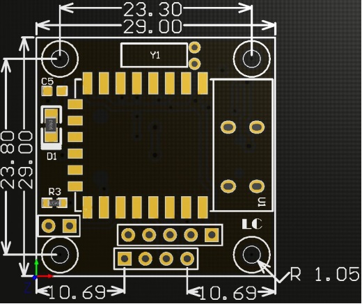
2.Interface introduction
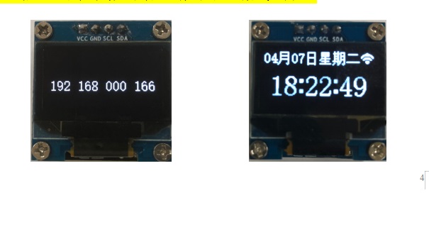
2.Waiting for the 15S module display appear WiFi icon in the upper right corner and the IP address indicates that the router has been successfully connected, then refresh the weather and date of the default city in Beijing, as shown below:
Factory firmware programming
For the secondary development customer wants to re-write the factory firmware, you can follow the steps below:
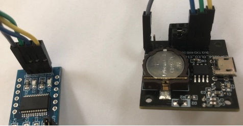
1.Using the jumper cap / DuPont cable to connect the IO0 and GND pins, prepare one TTL serial port module (for example :FT232) plug in computer usb,serial module and development board connect ways as below:
| TTL serial module | WiFi clock module |
| GND | GND |
| TX | RX |
| RX | TX |
| 3.3V | 3V3 |
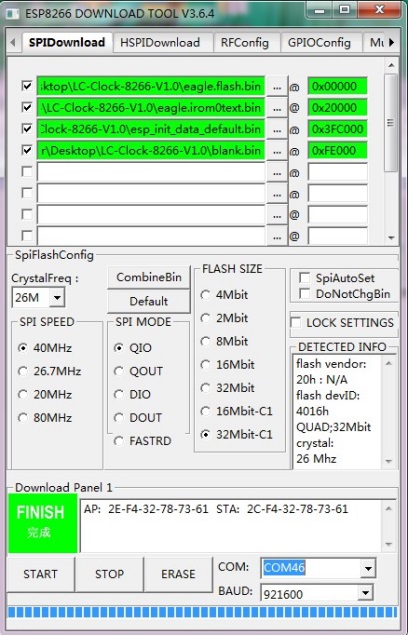
Using firmware programming software FLASH_DOWNLOAD_TOOLS_V3.6.4 open software. Setting burned address,port number and other parameters,you can click START. After the programming is completed, disconnect the connection between IO0 and GND then will be run, as follows:
Tips:
1.The above programming address is applicable to the factory firmware. For the second development,please according to the actual situation select the address.
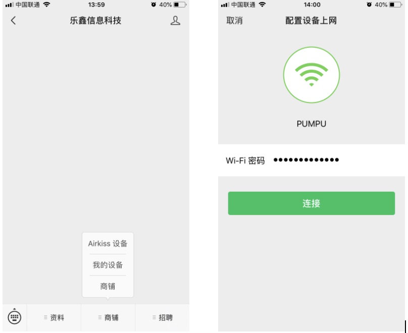
2.When you matching network for the clock module,router,clock module and mobile phone should be as close as possible.
3.During the matching process, the phone may prompt "configure wifi failed", do not care,as long as the clock module can display the WiFi icon and IP address,the matching network is successful.
4.Only provide factory firmware,does not provide ESP8266 source code under Eclipse!

© 2011-2023 Shenzhen LC Technology Co.,Ltd. All rights reserved.
Add:Room 301,Building No.3,Guole Technopark,Lirong Road,Dalang Street,Longhua District,Shenzhen 518110,China.
Tel:+86-755-82720811


Mobile station