Integrity - based innovation in science and technology Home|Favorite|Contact us
Name:Helen.
Tel:+86-755-82720811
E-mail:helen@chinalctech.com/helen@lctech-inc.com
Add:Room 301, Building No.3, Guole Technopark, Lirong Road, Dalang Street, Longhua District, Shenzhen 518110, China.
Online consultingModbus RTU 8 channel relay module RS485/TTL UART 8 channel input 8 channel output
SKU :LC-Modbus-8R-D7
Overview
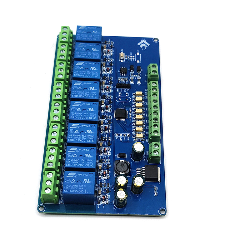
LC 8 channel Modbus relay module equipped with mature and stable 8-bit MCU and RS485 level communication chip,adopt standard MODBUS RTU format RS485 communication protocol ,It can realize 8 channel optocoupler input signal detection and 8 channel relay output, can be used for digital detection or power control occasions.
Functions:
1.Onboard mature and stable STM8S103K3T6 MCU and MAX485 level communication chip.
2.Communication protocol:support standard Modbus RTU protocol
3. Communication Interface:support RS485/5V Level TTL UART interface
4.Communication baud rate: 4800/9600/19200,default 9600bps, Support power-down save.
5.Optocoupler input signal range, DC3.3-30V(this input not available for relay control)
6.Output signal:relay switch signal, support manual control,flash OFF/ON mode,The delay base is 0.1S,the maximum allowable flash OFF/ON time is 0xFFFF*0.1S=65535*0.1S=6553.5S
7.Device address:range:1-255,default 255,Support power-down save
8.Baud rate/optocoupler input status/relay status/device address can be read by software/commands.
9.On-board 8 channel 5V,10A/250V AC 10A/30V DC relay,can continuously sucking 100,000 times, it has Diode flow protection for short response times.
10. On-board relay switch indicator.
11. reserve STM8 SWIM programming port, support customers' secondary development to download their own firmware
12.supply voltage:DC7-30V, adopt 5.08mm terminal power supply.
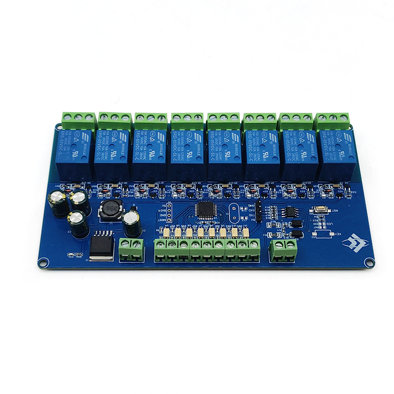
Introduced the hardware and instructions
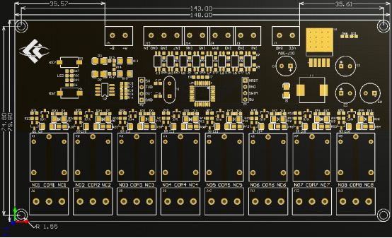
1.board size:143*79.8 (not include case) weight :145g(not include case)
2.interface description
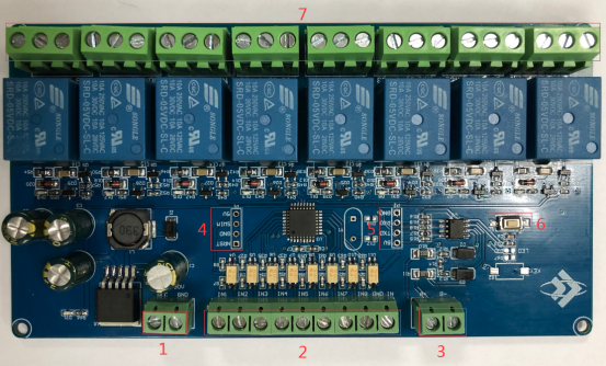
1,VCC,GND:DC7-30V 5.08mm power input terminal
2,DC3.3-30V Optocoupler signal input
IN1-IN8: channel 1-channel 8 positive
GND_IN:channel 1-channel 8 Common negative
3, A+,B-:RS485 communication Interface, A+, B- are respectively connected to A+, B- of the external control terminal.
4,5V,SWIM,GND,NRST:STM8 SWIM program download port.
5,TXD,RXD,GND:TTL level UART Communication Interface,TXD,RXD,GND respectively connected to the external control terminal RXD,TXD,GND,only support 5V level TTL module /MCU. Recommended wiring sequence :Modbus module power on - Modbus module connect TTL module -TTL module power on .
6,RST: MCU reset button
7,Relay switch signal output
NO:normally opened end,the NO disconnect with COM when relay released and connect with COM when relay closed.
COM: common end
NC:Normally closed end ,the NC disconnect with COM when relay closed and connect with COM when relay released
Modbus RTU introduction of instruction
Modbus device through receive from external control terminal (like Host computer/MCU )Modbus RTU instruction to perform related operations, one frame instruction generally consists of device address, function code, register address, register data, and check code,frame length is related to function code. Each frame date’s first byte is the device address.can set range on 1-255 default 255(scilicet 0xFF),the last 2byte is CRC check code.
suppose the device address is 255, the commonly used Modbus RTU instructions are as follows:
1, turn on the relay No. 1 (manual mode)
send : FF 05 00 00 FF 00 99 E4
return :FF 05 00 00 FF 00 99 E4
remarks:(1)send the 3--4th byte of the transmitted frame represents the relay address,the relay 1-relay 8 address are respectively 0x0000,0x0001,0x0002,0x0003,0x0004,0x0005,0x0006,0x0007.
(2)The 5--6th byte of the transmitted frame represents the data, 0xFF00 represent turn on relay,0x0000 represent turn off relay.
2, turn off the relay No. 1 (manual mode)
send: FF 05 00 00 00 00 D8 14
return: FF 05 00 00 00 00 D8 14
3, turn on the relay no.2 (manual mode)
send : FF 05 00 01 FF 00 C8 24
return : FF 05 00 01 FF 00 C8 24
4, turn off the relay No. 2 (manual mode)
send :FF 05 00 01 00 00 89 D4
return :FF 05 00 01 00 00 89 D4
5, turn on all relay
send :FF 0F 00 00 00 08 01 FF 30 1D
return :FF 0F 00 00 00 08 41 D3
6,turn off all relay
send:FF 0F 00 00 00 08 01 00 70 5D
return :FF 0F 00 00 00 08 41 D3
16, turn on no.1 relay (flash off mode 2S)
send :FF 10 00 03 00 02 04 00 04 00 14 C5 9F
return : FF 10 00 03 00 02 A4 16
remarks: the 3-4th byte of the transmitted frame is represent relay address,relay1-relay8’s address separately is 0x0003,0x0008,0x000D,0x0012,0x0017,0x001C,0x0021,0x0026 .
The 10th-11th byte of the transmitted frame represents the delay setting value, and the delay base is 0.1S, so the delay time is 0x0014*0.1=20*0.1S=2S, and the relay automatically turn off after turned on 2S
17,turn off no.1 relay (flash off mode 3S)
send :FF 10 00 03 00 02 04 00 02 00 1E A5 99
return :FF 10 00 03 00 02 A4 16
Remarks : (1)The 3th-4th byte of the transmitted frame is represent relay address,relay1-relay8’s address separately is 0x0003,0x0008,0x000D,0x0012,0x0017,0x001C,0x0021,0x0026
(2)The 10th-11th byte of the transmitted frame represents the delay setting value, and the delay base is 0.1S, so the delay time is 0x001E*0.1=30*0.1S=3S
4,Simple instructions
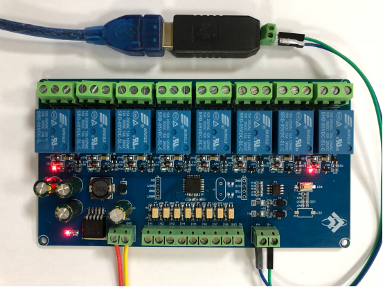
Modbus relay module can via RS485/TTL UART interface received from host computer /MCU’s Modbus RTU command to perform related operations.The following is an example of using the host computer software via the RS485 interface to open relay 1 and 2 (manual mode),suppose device address for 255.baud rate is 9600,Then steps of usage as follows:
1,5.08mm terminal’s VCC,GND connect power supply.
2, A+,B- : respectively USB turn RS485 module output terminal A+ and B-
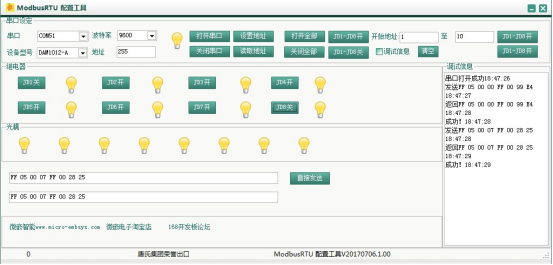
3,turn on host computer software ModbusRTU configuration Tool,choose correct port number, baud rate is 9600.default address is 255,click open serial ports
4, then click ”JD1 ON” button can turn on relay 1 and 8 ,meanwhile indicator of relay lights up .as below:
5,How to generate check code
Modbus RTU command are send through upper PC software (like:ModbusRTU configuration Tool ),CRC check code is auto generated, if want use serial debugging software (like SSCOM )to test Modbus relay module then need manually generated
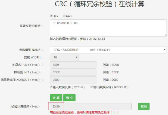
4,Exchange checksum calculation result E499 high and low byte position then get CRC check code 99E4,and complete transmission frame:FF 05 00 00 FF 00 99 E4
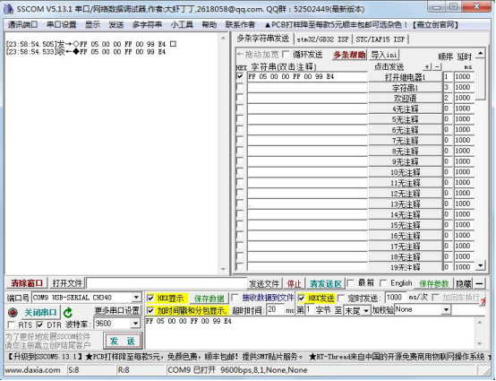
5,Through serial port debugging software SSCOM V5.13.1 use the transmission frame send to modbus relay module can open first way relay (manual mode),as bellow:
Please refer our date if you need more detailed instructions and usage of way in host computer control modbus relay
© 2011-2020 Shenzhen LC Technology Co.,Ltd. All rights reserved.
Add:Room 301, Building No.3, Guole Technopark, Lirong Road, Dalang Street, Longhua District, Shenzhen 518110, China.
Tel:+86-755-82720811


Mobile station