Integrity - based innovation in science and technology Home|Favorite|Contact us
Name:Helen.
Tel:+86-755-82720811
E-mail:helen@chinalctech.com/helen@lctech-inc.com
Add:Room 301, Building No.3, Guole Technopark, Lirong Road, Dalang Street, Longhua District, Shenzhen 518110, China.
Online consulting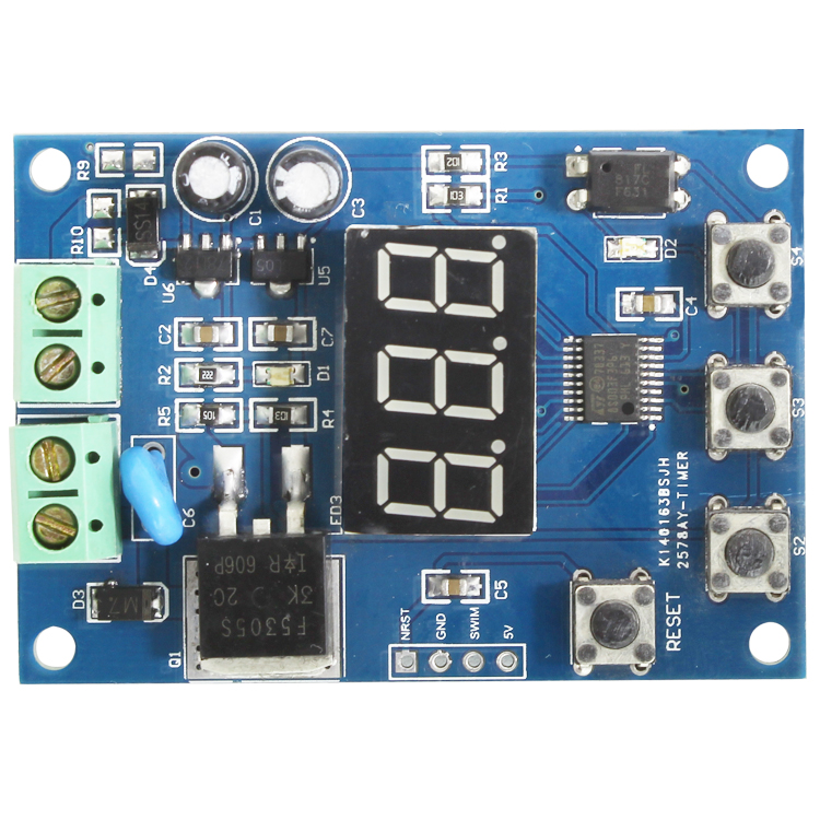
Steps for setting mode 2
(1)press the mode key S2 (display "p-1."), and then change the mode value by S3(1--4 optional)
(2)Press S2, the dot is positioned at the 100 position of the time T1 of the relay, and then changes the 100 position value of T1 by press S3 (0--9 optional).
(3)Repeat steps 2 twice to set the tens and the ones place of T1 respectively.;
(4)Press S2, the dot is positioned at the 100 position of the time T2 of the relay, and then changes the 100 position value of T2 according to S3 (0--9 optional).
(5)Repeat steps 4 twice to set the tens and the ones place of T1 respectively.;
(6)Press S2 to exit ,small dot disappear;
(7)press S4, MOS tube is through , the LED light D2 is on , the value is -1,means that it work properly;
(8)
The MOS tube will brake off automatically when T1 is over ,LED light D2 is out ,Digital tube shows T2 countdown. The MOS tube will connect when T2 is over ,LED light D2 is on ,digital tube shows T1 countdown ....repeat again and again
(9)press S4 to stop timing when it is on timer 1,and digital tube shows 000 .When it is on timer T2,press S4 to restart timing T1,T2 based on the former setting time .
Functions :
1.It has strong anti-interference capability ,good stability because its structure ofonboard STM8S high performance microprocessor and EL817,
2.three digital LED of panel shows real time
3.long span forMOS tube,could work no quantity limit,maximum current output 5A;
4.with output terminal voltage indicator(D2).LED is on and represents MOS tube conduction, output voltage is equal to VCC; When LED is out,the MOS tube is off, the output voltage is 0.
5.On board 4 button 6X6mm(onefor reset,3 functional button);
6.MOS tube lead duration(T1)&MOS tube duration of turn off(T2)could set separately;
7.four modes are optional : first mode :one timing per 1-9999minutessecond mode :cycle timing per 1-999minutesThird mode : one timing per 1-999sFourth mode :cycle timing per 1-999s
8.work current:40mA;
9.work voltage:DC 12V-24V;
10. voltage output:DC 12V-24V;
11.The board size:60*42mm
1 Interface instruction :
VCCGND : positive and negative of working pressure
OUT+ OUT- : positive and negative of outputpressure
2.function for button
RST: reset button ,reset to fault factory setting
S1: mode button ,set working mode and timer time
S2 : reduce /add button ,set exact value of mode and timing
S3:Start/stop button,
Start button :connect MOS tube and and work again based on former setting time
Stop button :turn off MOS tube and stop timing (display show "000")
It goes to mode and timing setting by press S2 . Continuous press S2 to move the small dot, dot location where represents value . Press S3 to set mode and periodic time T1 and T2 (set T1only when it is on Mode1 and mode 3 ).press S2 to exit .At this moment,the small dot disappear, then press start button S4, MOS tube is through , the LED light D2 is on , the value is -1,means that it work properly to begin.
Setting method for mode 1 is same as mode 3,mode2 is same as mode 4.Now,we take mode 1 and mode 2 setting for example :
Steps for setting mode 1
(1)press the mode key S2 (display "p-1.") after power on , and then change the mode value by S3(1--4 optional)
(2)Press S2, the dot is positioned at the 100 position of the time T1 of the MOS tube, and then changes the 100 position value of T1 by press S3 (0--9 optional).
(3)Repeat steps 2 twice to set the tens and the ones place of T1 respectively.
(4)Press S2 to exit ,small dot disappear
(5)press button S4, MOS tube is through , the LED light D2 is on , the value is -1,means that it work properly to begin
(6)The MOS tube will be off automatically when T1 is over ,LED D2 will be out also ,and led display show "000"
(7)Press S4 to continue the former setting time when MOS tube is through again . In addition, It will turn off MOS tube if press S4 again and timing is over ,LED display shows"000",
Steps for setting mode 2
(1)press the mode key S2 (display "p-1."), and then change the mode value by S3(1--4 optional)
(2)Press S2, the dot is positioned at the 100 position of the time T1 of the relay, and then changes the 100 position value of T1 by press S3 (0--9 optional).
(3)Repeat steps 2 twice to set the tens and the ones place of T1 respectively.;
(4)Press S2, the dot is positioned at the 100 position of the time T2 of the relay, and then changes the 100 position value of T2 according to S3 (0--9 optional).
(5)Repeat steps 4 twice to set the tens and the ones place of T1 respectively.;
(6)Press S2 to exit ,small dot disappear;
(7)press S4, MOS tube is through , the LED light D2 is on , the value is -1,means that it work properly;
(8)The MOS tube will brake off automatically when T1 is over ,LED light D2 is out ,Digital tube shows T2 countdown. The MOS tube will connect when T2 is over ,LED light D2 is on ,digital tube shows T1 countdown ....repeat again and again
(9)press S4 to stop timing when it is on timer 1,and digital tube shows 000 .When it is on timer T2,press S4 to restart timing T1,T2 based on the former setting time .
© 2011-2020 Shenzhen LC Technology Co.,Ltd. All rights reserved.
Add:Room 301, Building No.3, Guole Technopark, Lirong Road, Dalang Street, Longhua District, Shenzhen 518110, China.
Tel:+86-755-82720811


Mobile station