Integrity - based innovation in science and technology Home|Favorite|Contact us
Name:Helen.
Tel:+86-755-82720811
E-mail:helen@chinalctech.com/helen@lctech-inc.com
Add:Room 301, Building No.3, Guole Technopark, Lirong Road, Dalang Street, Longhua District, Shenzhen 518110, China.
Online consultingSKU :LC-Relay-ESP01-4R-5V
Tech info : https://www.mediafire.com/file/jwjwjuycxed6e1h/LC-Relay-ESP01-4R_EN.zip/file
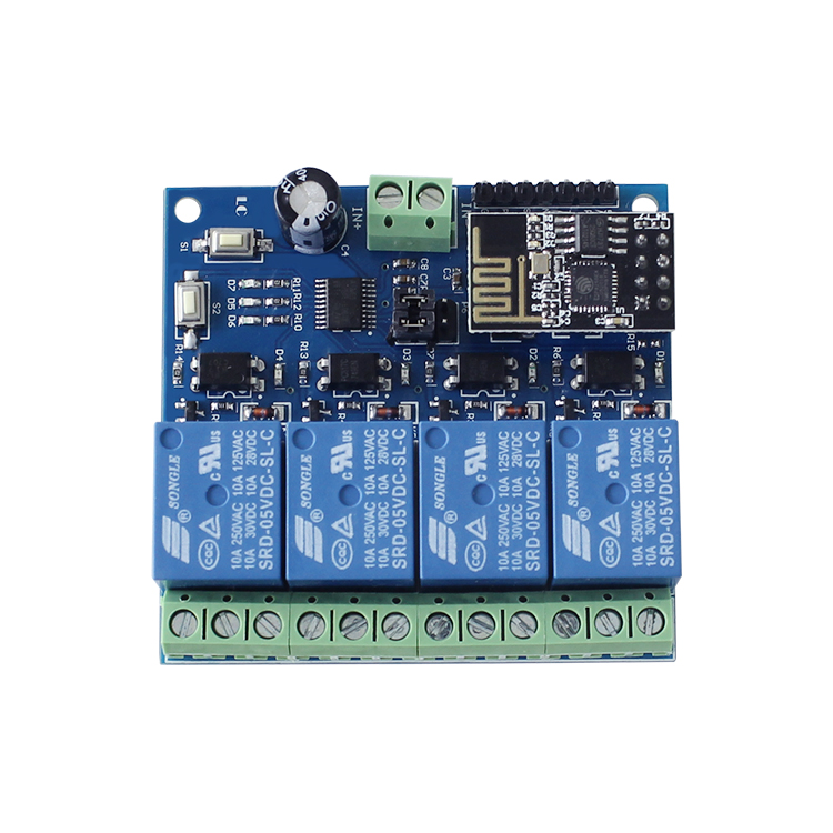
1.on board high quality MCU and ESP-01WIFI module
2.two working mode :
Mode 1:cellphone carry on wifi module directly
Mode 2: cellphone and wifi module carry on router together
Additional function :work as USB module when disconnect ESP-01 module
3.Transmission distance:
(1) the open environment, the mobile phone when carrying on the WIFI module maximum transmission distance of 100 m;
(2), when the WiFI module and cell phone carrying on the router at the same time the signal transmission distance depends on router signal
4.Use the Smartconfig technology to complete the configuration of the account and password of the esp-01 WIFI module on the mobile APP. The configured account and password will be memorized after power off
5.The board contains 5V,10A/250V AC 10A/30V DC relay, which can continuously absorb 100,000 times, with the protection of diode current and short response time.
6.With mode option and working statue LED indicator
7.With 4 isolator and strong anti interference ability
8.Reserved UART debug interface and MCU download port for program
Hardware introduction :
Board size:60*63mm
1,interface on board:
IN+,IN-:5V voltage input;
5V,GND,TX,RX:UART serial port PIN;
SWIM,PIN8,NRST:reserved MCU download port;
Button S1:change mode,default mode is mode 1
Button S2:reset
LED D1/D2/D3/D4(red):relay working LED,LED on when relay is on
LED D7(red):indicator for mode 1
LED D5(blue):indicator for mode 2
LED D6(green):work statue indicator,exact details as below:
(1)When extinguished, it is being configured or disconnected from the router.
(2)0.5s fast blinking represents cellphone app is configuring WIFI account and password for ESP-01 module
(3)2S slow blinking to configure finished ,and wait for connection with cellphone by TCP
(4)LED always on represents TCP connections with mobile phone successfully
Connection for reserved two cap jumper :
Generally ,insert them to bottom ,that is RX to RX1,TX to TX1 .Insert them to upper ,when use it as USB module
COM1 COM2 COM3 COM4:Common terminal;
NC1 NC2 NC3 NC4:normal close
NO1 NO2 NO3 NO4:normal open
Control command for relay(hex format):
Open relay 1:A0 01 01 A2
Close relay 1:A0 01 00 A1
Open relay 2:A0 02 01 A3
Close relay 2:A0 02 00 A2
Open relay 3:A0 03 01 A4
Close relay 3:A0 03 00 A3
Open relay 4:A0 04 01 A5
Close relay 4:A0 04 00 A4
Tips: all of the following are used to control the first 2 relay in the mobile phone APP. The third and fourth way are the same, except that the relay control instructions are different.
2,get ready for the following software and tools:(1)5V/1A adaptor and connect to IN+ and IN-;
(2)Install APP "EspTouch_Demo" android version to configure wifi account and password for ESP-01 module on the first time of mode 2
© 2011-2020 Shenzhen LC Technology Co.,Ltd. All rights reserved.
Add:Room 301, Building No.3, Guole Technopark, Lirong Road, Dalang Street, Longhua District, Shenzhen 518110, China.
Tel:+86-755-82720811


Mobile station