Integrity - based innovation in science and technology Home|Favorite|Contact us
Name:Helen.
Tel:+86-755-82720811
E-mail:helen@chinalctech.com
Add:Room 301,Building No.3,Guole Technopark,Lirong Road,Dalang Street,Longhua District,Shenzhen 518110,China.
Online consulting
| TTL serial port module | STM32 Minimum Development Board |
| GND | GND |
| TX | RX |
| RX | TX |
| 3.3V | 3.3V |
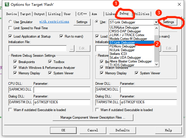
| Link debugger | STM32 Minimum Development Board |
| GND | GND |
| SWCLK | CLK |
| SWDIO | DIO |
| 3.3V | 3.3V |
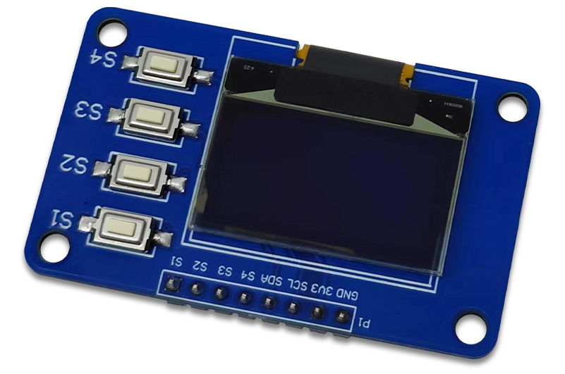
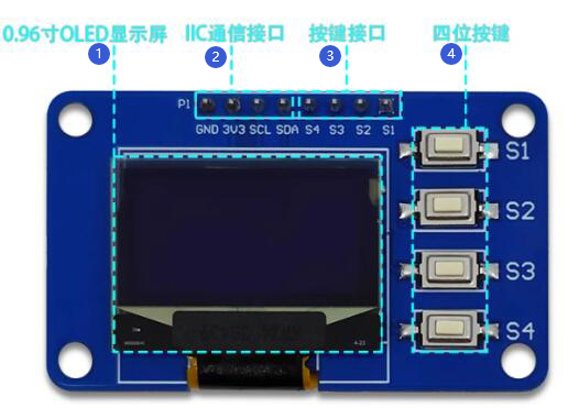
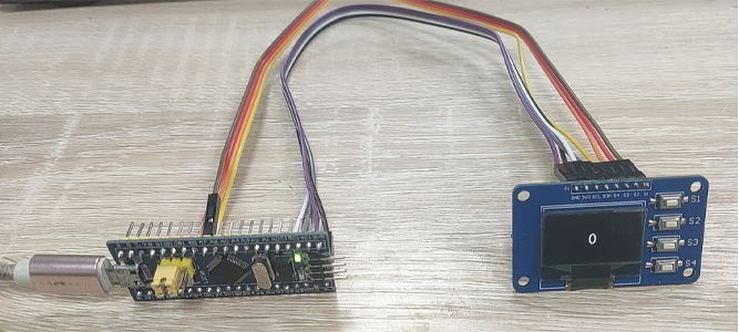
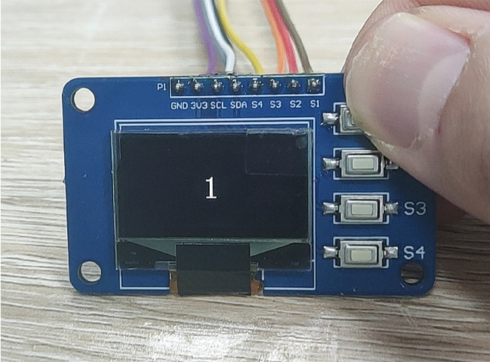
| Display module | STM32 Minimum Development Board |
| GND | GND |
| 3.3V | 3.3V |
| SCL | PB8 |
| SDA | PB9 |
| S4 | PA10 |
| S3 | PA9 |
| S2 | PA8 |
| S1 | PA7 |
© 2011-2024 Shenzhen LC Technology Co.,Ltd. All rights reserved.
Add:Room 301,Building No.3,Guole Technopark,Lirong Road,Dalang Street,Longhua District,Shenzhen 518110,China.
Tel:+86-755-82720811

Mobile station