Integrity - based innovation in science and technology Home|Favorite|Contact us
Name:Helen.
Tel:+86-755-82720811
E-mail:helen@chinalctech.com
Add:Room 301,Building No.3,Guole Technopark,Lirong Road,Dalang Street,Longhua District,Shenzhen 518110,China.
Online consulting
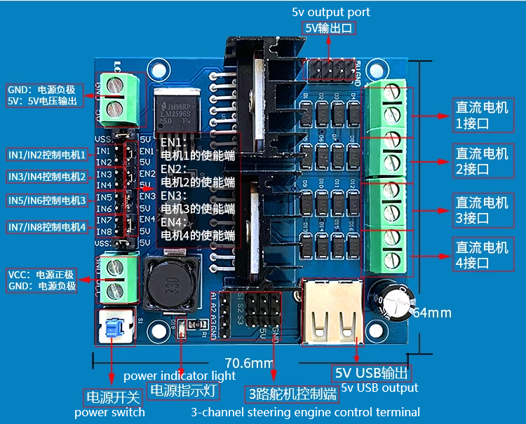

| Working mode | H-bridge driver (4 channels) | Main control chip | 2 dual H-bridge L298N chips |
|
Drive voltage VSS1 and VSS2 (default 5V) |
5-30V | Power chip | LM2596-5.0 switching power supply, superior to LM7805 |
| Logic voltage | 5V | Logic current | 0-36mA |
| Supply voltage VCC (recommended value) | 7-12V | Supply voltage VCC (limit value) | 6-30V |
| Single bridge maximum driving current | 2A | maximum total power consumption | 20W |
| DC motor | rotation mode | IN1 | IN2 | IN3 | IN4 | IN5 | IN6 | IN7 | IN8 |
| M1 | Forward rotation | High | Low | ||||||
| M1 | Reverse | Low | High | ||||||
| M1 | Stop | Low | Low | ||||||
| M2 | Forward Rotation | High | Low | ||||||
| M2 | Reverse | Low | High | ||||||
| M2 | Stop | Low | Low | ||||||
| M3 | Forward Rotation | High | Low | ||||||
| M3 | Reverse | Low | High | ||||||
| M3 | Stop | Low | Low | ||||||
| M4 | Forward Rotation | High | Low | ||||||
| M4 | Reverse | Low | High | ||||||
| M4 | Stop | Low | Low |
© 2011-2024 Shenzhen LC Technology Co.,Ltd. All rights reserved.
Add:Room 301,Building No.3,Guole Technopark,Lirong Road,Dalang Street,Longhua District,Shenzhen 518110,China.
Tel:+86-755-82720811


Mobile station