Integrity - based innovation in science and technology Home|Favorite|Contact us
Name:Helen.
Tel:+86-755-82720811
E-mail:helen@chinalctech.com
Add:Room 301,Building No.3,Guole Technopark,Lirong Road,Dalang Street,Longhua District,Shenzhen 518110,China.
Online consultingSKU: LC-AI-K210-7Mic
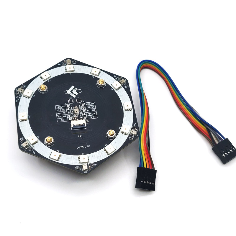
Overview
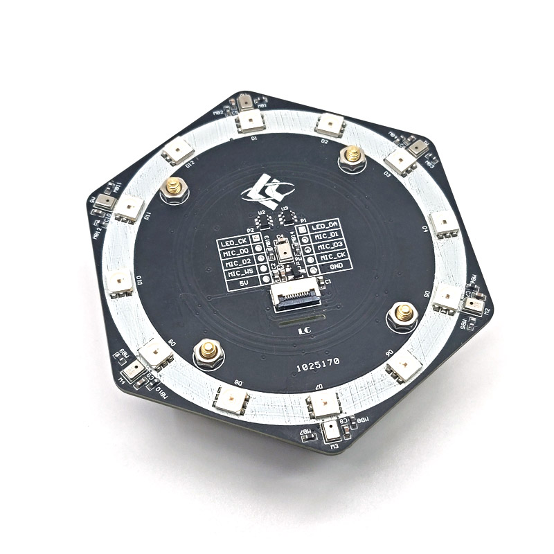
LC 6+1 Mic Array module carry 7 high quality Silicon microphone and 12 Programmable full color LED,Can be used for voice recognition capture, sound source localization, LED full color display and other occasions.
Function features
1.Silicon microphone parameter
(1)Onboard 6+1 MSM261S4030H0R Silicon microphone,support right and left channel output, 3 left channel MIC(M0/M2/M4)+3right channel MIC(M1/M3/M5)+1 right channel MIC(M6)
(2)Communication Interface:12s
(3)Sound pressure level:140db SPL
(4)Level of sensitivity: -26(dB,dBFS @1KHz 1Pa)
(5)Signal to noise ratio: 57dB(20KHz bandwidth, A-weighted)
(6)HD<1%(100dB SPL @1KHz S=Nom, Rload>2K)
(7)Clock frequency:1.0-4.0MHz (Normal mode),150-800KHz (low power mode)
2.12 Programmable full color LED
(1)Onboard 12 cascaded SK9822 built-in IC full-color LEDs, which can be controlled by only 2 MCU I / Os
(2)Communication interface: two-wire synchronous control signals CKI and SD
(3)Viewing angle: 120 degrees
(4)Two-wire synchronous selection of positive or negative output RGB three color LED output
(5)each LED each color Consumption current 20mA,Full color maximum current consumption current 60mA
3.Onboard interface: 2.54mm 2*5P Horns/ 2.54mm single pin /0.5mm 10P FPC base.
4.Scope of application: Our K210 Dock development board can also be driven by other MCUs with I2S interface.
Hardware introduction and description
1.Board size: 89.7*78.8mm, weight: 44g (include fitting)
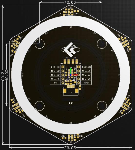
Interface introduction
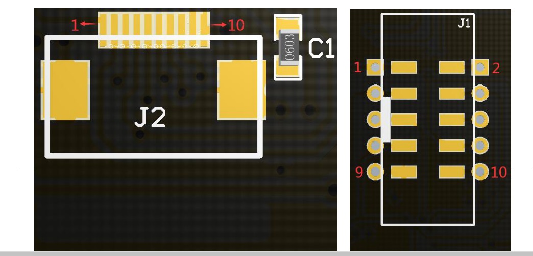
A.0.5mm 10P FPC base B.2.54mm 2*5P Horns
| Pin number | Pin name | Function description | |
| FPC base | Horns | ||
| 1 | 2 | LED_CK | SK9822 RGB Clock input CKI |
| 2 | 1 | LED_DA | SK9822 RGB data input SDI |
| 3 | 4 | MIC_D0 | Microphone M0、M1Serial data output SDATA |
| 4 | 3 | MIC_D1 | Microphone M2、M3 Serial data output SDATA |
| 5 | 6 | MIC_D2 | Microphone M4、M5 Serial data output SDATA |
| 6 | 5 | MIC_D3 | Microphone M6 Serial data output SDATA |
| 7 | 8 | MIC_WS | Frame clock for all microphones WS |
| 8 | 7 | MIC_CK | Bit clock for all microphones BCLK |
| 9 | 10 | 5V | Power 5V |
| 10 | 9 | GND | Power ground |
© 2011-2023 Shenzhen LC Technology Co.,Ltd. All rights reserved.
Add:Room 301,Building No.3,Guole Technopark,Lirong Road,Dalang Street,Longhua District,Shenzhen 518110,China.
Tel:+86-755-82720811


Mobile station