Integrity - based innovation in science and technology Home|Favorite|Contact us
Name:Helen.
Tel:+86-18927473783
E-mail:helen@chinalctech.com
Add:Room 301,Building No.3,Guole Technopark,Lirong Road,Dalang Street,Longhua District,Shenzhen 518110,China.
Online consultingSKU :LC-Relay-ESP12-1R-D8
Overview:
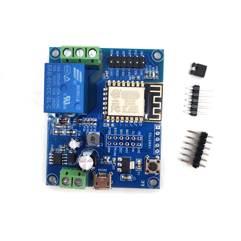
LC ESP826 Single way relay development board carry on ESP-12F WiFi module I/O port is fully extracted, support DC8-80V/USB 5V and other power supply methods. Supply Arduino development environment reference code, suitable for ESP8266 secondary develop learning, smart home wireless control and other occasions.
Features
1.onboard mature and stable ESP-12F WiFi module ,High capacity4M Byte Flash.
2. I/O port of the WiFi module and the download port of the UART program are all taken out to facilitate secondary development.
3.Support DC8-80V/USB5V/ Pin header power supply.
4.onboard WiFi module RST reset button
5.ESP-12F support for development tools such as Eclipse/Arduino IDE,provide reference programs in the Arduino development environment
6.Onboard 1 channel 5V relay,output switch signal ,Suitable for controlling and controlling the working voltage to be within the load of AC 250V/DC30V.
7.Onboard power indicator ,1 programmable LED and relay indicator
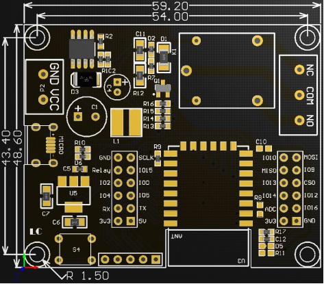
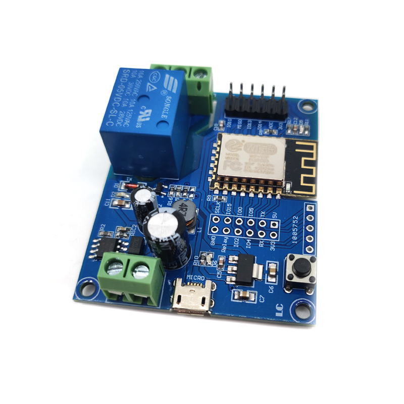
Hardware introduction and description
1.board size : 59.2*48.6mm
Weight :26g
introduce of interface
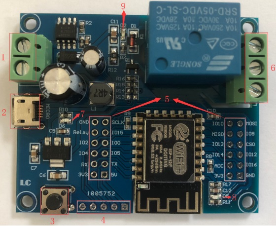
1,VCC,GND: DC8-80V power supply
2,Micro USB:DC5V USB power supply
Mark: DC8-80V/DC5V USB/ Pin header 5V Choose one of the three power supply methods.
3. 6X6mm press button, ESP8266 reset button
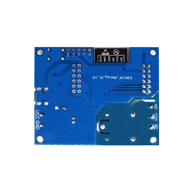
4. UART Program download port: ESP8266 GND,RX,TX,5V separately connect external TTL Serial module GND,TX,RX,5V, IO0 need with GND connect when download, disconnect the connection between IO0 and GND After the download is complete.
5.GPIO Pinout port
6. relay output end:
NC: Normally close,the NC disconnect with COM when relay closed and connect with COM when relay released.
COM: Common end
NO: Normally open end,the NO disconnect with COM when relay released and connect with COM when relay closed.
7.Power indicator LED
8.programmable LED,using GPIO16 control .
9.Relay indicator LED.when connect will light .
GPIO Pinout port introduce
| NO. | Name | Function | NO. | Name | Function |
| 1 | GND | Power ground | 13 | IO10 | GPIO10 |
| 2 | Relay | Relay drive port , using IO5 drive by default. If need use other I/O drive relay, please remove R14, then use the I/O connected to this relay pin. | 14 | MISO |
Slave output master input |
| 3 | IO2 | GPIO2; UART1_TXD | 15 | IO13 | GPIO13; HSPI_MOSI; UART0_CTS |
| 4 | IO4 | GPIO4 | 16 | IO14 | GPIO14; HSPI_CLK |
| 5 | RX | UART0_RXD; GPIO3 | 17 | ADC | A/D Conversion result. Input voltage range 0~1V, ranging from 0 to 1024 |
| 6 | 3V3 | 3.3V power | 18 | 3V3 | 3.3V power |
| 7 | SCLK | CLOCK | 19 | MOSI | Master output Slave input |
| 8 | IO15 | GPIO15; MTDO; HSPICS; UART0_RTS | 20 | IO9 | GPIO9 |
| 9 | IO0 | GPIO0 | 21 | CS0 | chip select |
| 10 | IO5 | GPIO5 | 22 | IO12 | GPIO12; HSPI_MISO |
| 11 | TX | UART0_TXD; GPIO1 | 23 | IO16 | GPIO16 |
| 12 | 5V | 5Vpower | 24 | GND | Power ground |
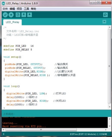
Arduino development environment building
ESP8266 support Eclipse/Arduino IDE development tools, use Arduino will easy,Arduino development environment build way as below:
1. Install Arduino IDE 1.8.9 or latest version
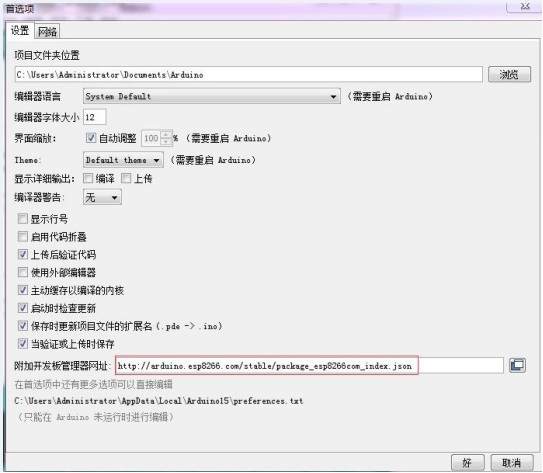
2. Open Arduino IDE ,Click on File - Preferences in the menu bar,Click on Add URL in the "Additional Development Board Manager URL" after entering the preferences:
http://arduino.esp8266.com/stable/package_esp8266com_index.json,
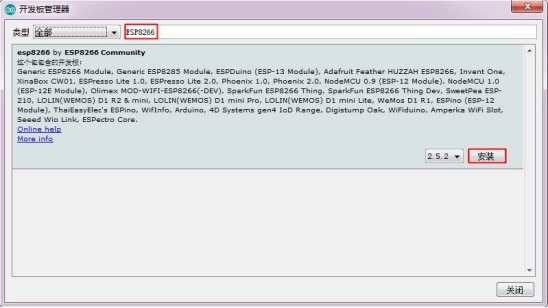
3.Click menu’s tool --development board -development manager, search for "ESP8266" to install Arduino support package for ESP8266 2.5.2 or the latest version
Program download:
1. Use the jumper cap to connect the IO0 and GND pins, prepare one TTL serial module(such as :FT232) plug into computer USB, serial module and development board connecting way as below:
| TTL serial module | ESP8266 development board |
| GND | GND |
| TX | RX |
| RX | TX |
| 5V | 5V |
2.click menu bar tool--development board ,choose development board for ESPino (ESP-12 module)
3. open need download program,click menu bar’s tool---interface Choose the correct port number
4.after click upload program will automatically compile and download to the development board,as below:
5. Finally cut IO0 with GND connect, the board can be powered up by pressing the power button again or by pressing the reset button.
© 2011-2025 Shenzhen LC Technology Co.,Ltd. All rights reserved.
Add:Room 301,Building No.3,Guole Technopark,Lirong Road,Dalang Street,Longhua District,Shenzhen 518110,China.
Tel:+86-18927473783


Mobile station