Integrity - based innovation in science and technology Home|Favorite|Contact us
Name:Helen.
Tel:+86-18927473783
E-mail:helen@chinalctech.com
Add:Room 301,Building No.3,Guole Technopark,Lirong Road,Dalang Street,Longhua District,Shenzhen 518110,China.
Online consulting
Overview
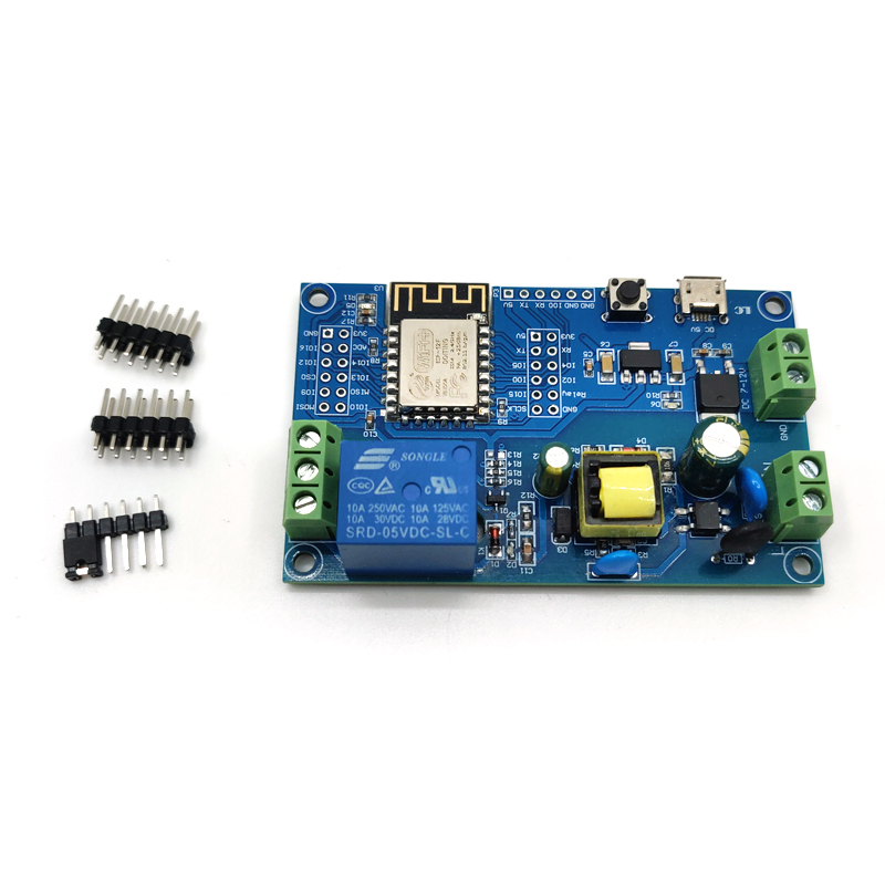
LC ESP8266 single relay development board onboard ESP-12F WiFi module, I/O orifice full lead ,support AC90-250V/DC7-12V/USB 5V etc. many supply power way. Provide Arduino develop environment reference code,suit for ESP8266 secondary development study, smart home wireless control.
Function features
Hardware introduction and description
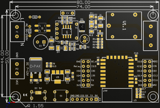
1.Board size: 80*50mm Weight: 34g
2.Introduce of interface
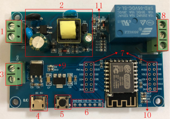
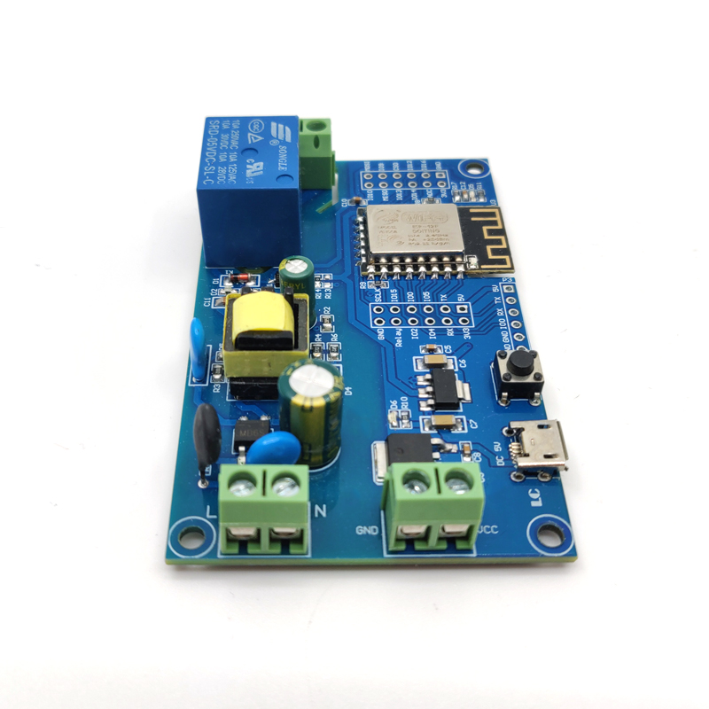
1.L,N: AC90-250V power supply
2.AC90-250V turn DC5V switch power supply (when adopt AC supply power please don’t directly touch here by hand !!! )
3.VCC,GND:DC7-12V power supply
4.Micro USB:DC5V USB power supply
Mark: AC90-250V,DC7-12V,DC5V USB Choose one of the three power supply methods
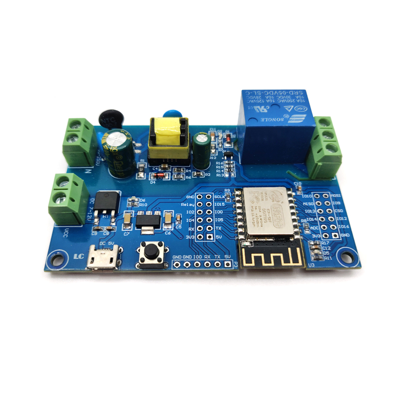
5.6X6mm press button, ESP8266 reset button
6. UART Program download port: ESP8266 GND,RX,TX,5V separately connect external TTL Serial module GND,TX,RX,5V, IO0 need with GND connect when download
7.GPIO Pinout port
8.Relay output end:
NC: Normally close,the NC disconnect with COM when relay closed and connect with COM when relay released
COM: Common end
NO: Normally open end,the NO disconnect with COM when relay released and connect with COM when relay closed
9.Power indicator LED
10.Programmable LED
11.Relay indicator LED
3.GPIO Pinout port introduce
| NO. | Name | Function | NO. | Name | Function |
| 1 | GND | Power ground | 13 | IO10 | GPIO10 |
| 2 | Relay | Relay drive port , using IO5 drive by default. If need use other I/O drive relay, please remove R14, then use the I/O connected to this relay pin. | 14 | MISO |
Slave output master input |
| 3 | IO2 | GPIO2; UART1_TXD | 15 | IO13 | GPIO13; HSPI_MOSI; UART0_CTS |
| 4 | IO4 | GPIO4 | 16 | IO14 | GPIO14; HSPI_CLK |
| 5 | RX | UART0_RXD; GPIO3 | 17 | ADC | A/D Conversion result. Input voltage range 0~1V, ranging from 0 to 1024 |
| 6 | 3V3 | 3.3V power | 18 | 3V3 | 3.3V power |
| 7 | SCLK | CLOCK | 19 | MOSI | Master output Slave input |
| 8 | IO15 | GPIO15; MTDO; HSPICS; UART0_RTS | 20 | IO9 | GPIO9 |
| 9 | IO0 | GPIO0 | 21 | CS0 | chip select |
| 10 | IO5 | GPIO5 | 22 | IO12 | GPIO12; HSPI_MISO |
| 11 | TX | UART0_TXD; GPIO1 | 23 | IO16 | GPIO16 |
| 12 | 5V | 5V power | 24 | GND | Power ground |
4.Arduino development environment building
ESP8266 support Eclipse/Arduino IDE development tools, use Arduino will easy,Arduino development environment build way as below:
(1)Install Arduino IDE 1.8.9 or latest version
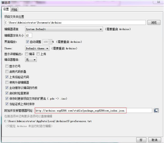
(2)Open Arduino IDE ,Click on File - Preferences in the menu bar,Click on Add URL in the "Additional Development Board Manager URL" after entering the preferences:
http://arduino.esp8266.com/stable/package_esp8266com_index.json,
(3)Click menu’s tool --development board -development manager, search for "ESP8266" to install Arduino support package for ESP8266 2.5.2 or the latest version
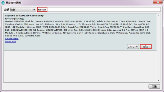
Note: because the download website is foreign, the access speed is slow.There may be a download error,please try again when you have good internet status.
Program download:
1. Use the jumper cap to connect the IO0 and GND pins, prepare one TTL serial module(such as: FT232) plug into computer USB, serial module and development board connecting way as below:
| TTL serial module | ESP8266 development board |
| GND | GND |
| TX | RX |
| RX | TX |
| 5V | 5V |
2.click menu bar tool--development board ,choose development board for ESPino (ESP-12 module)
3. open need download program,click menu bar’s tool---interface Choose the correct port number
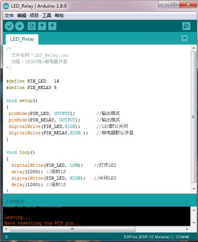
4.after click upload program will automatically compile and download to the development board,as below:
5. Finally cut IO0 with GND connect, the board can be powered up by pressing the power button again or by pressing the reset button.
© 2011-2025 Shenzhen LC Technology Co.,Ltd. All rights reserved.
Add:Room 301,Building No.3,Guole Technopark,Lirong Road,Dalang Street,Longhua District,Shenzhen 518110,China.
Tel:+86-18927473783


Mobile station