Integrity - based innovation in science and technology Home|Favorite|Contact us
Name:Helen.
Tel:+86-755-82720811
E-mail:helen@chinalctech.com
Add:Room 301,Building No.3,Guole Technopark,Lirong Road,Dalang Street,Longhua District,Shenzhen 518110,China.
Online consulting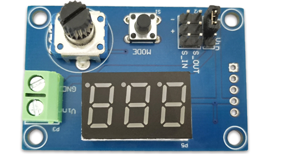
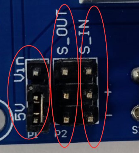
Use a jumper cap on the far left to switch the servo drive voltage to 5V below. Switch to the input power voltage above, it is recommended not to exceed 6.5V and can withstand a maximum of 12V
The middle is the servo drive end, the top is the signal, the middle is the power supply (voltage selected from the left jumper cap), and the bottom is the ground
The rightmost side is the servo signal input terminal, the top is the input signal, the middle is empty, and the bottom is the ground
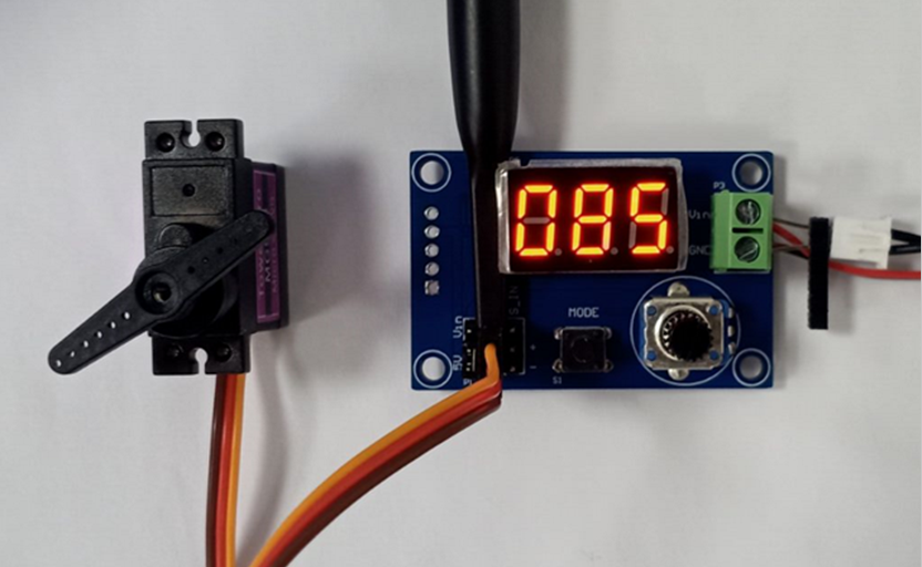
Connect the green terminal on the far right to the power supply, with a range of 5-12V
When powered on, the default driving mode is to twist the potentiometer, and the digital display will change. The displayed number is the high-level time, measured in units of 10us. Example: 85 represents a high level of 850us, with an adjustment range from 500us to 2500us and an accuracy of 2%
Pressing the button is in capture mode. If there is no signal connection, 000 will be displayed. When the signal is connected, the high-level time can be viewed in units of 10us
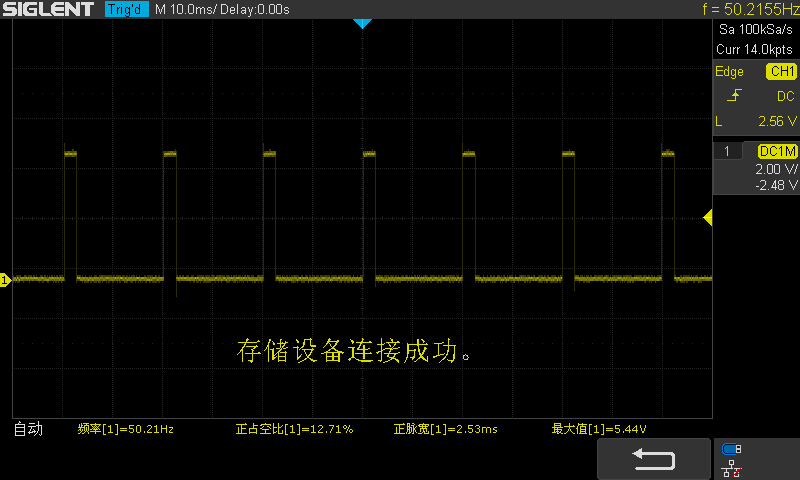
Actual measurement of output signal:2.5ms
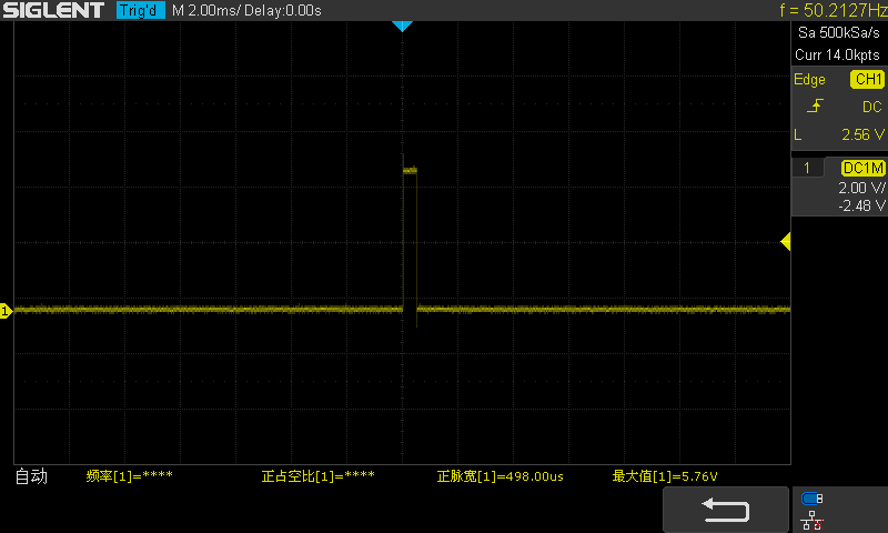
0.5ms
© 2011-2024 Shenzhen LC Technology Co.,Ltd. All rights reserved.
Add:Room 301,Building No.3,Guole Technopark,Lirong Road,Dalang Street,Longhua District,Shenzhen 518110,China.
Tel:+86-755-82720811


Mobile station