Overview
STM32 16channel steering controller is new high accuracy steer controlling module of LC .It adopts the internal PWM generator resource of 32-bit ARM chip,which generates PWM pulse control signal.It can control 16 steering gears at the same time at any Angle and precise time,quickly and precisely.
Function features
1.Using 32bit STM32F103C8T6 ARM main chip
2.Onboard 16M bytes large flash memory chip,can store up to 254 offline action groups.
3.Supports both online and offline operation modes,which can be controlled by PC terminal software, external MCU, onboard keys, or bluetooth APP.
4.Control channel number: 16,steering control accuracy: 0.09 degree (i.e. PWM minimum change value 1us)
5.The support control cycle is 20ms and the pulse width of steering gear is from 0.5-2.5ms (such as Futaba, huisheng, etc.)
6.Provide supporting Windows PC software and beta APP.
7.The steering gear and the control chip can be used independently or single-source power supply by the jumper cap. When plugged in,it can be supplied with a single power supply.
8.The on board special large current power switch and the 16 road 1.5A self-restore fuse, provides effective protection for control board and steering gear.
9.Power supply voltage: chip VIN pin terminal 5-9v; The power supply voltage of the steering gear is determined by the parameters of the specific steering gear.
10.Onboard STM32 UART (baud rate 9600, compatible with 3.3V and 5V level) communication control interface and SWD debugging interface.
11.Reserved the hc-05/06 bluetooth interface from the machine module,execute the stored action group by mobile APP instruction on offline mode
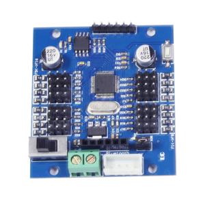
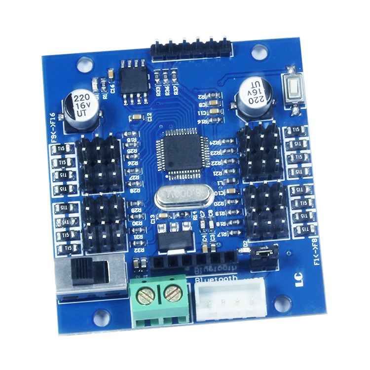
Hardware introduction
1.Board size: 49*54mm
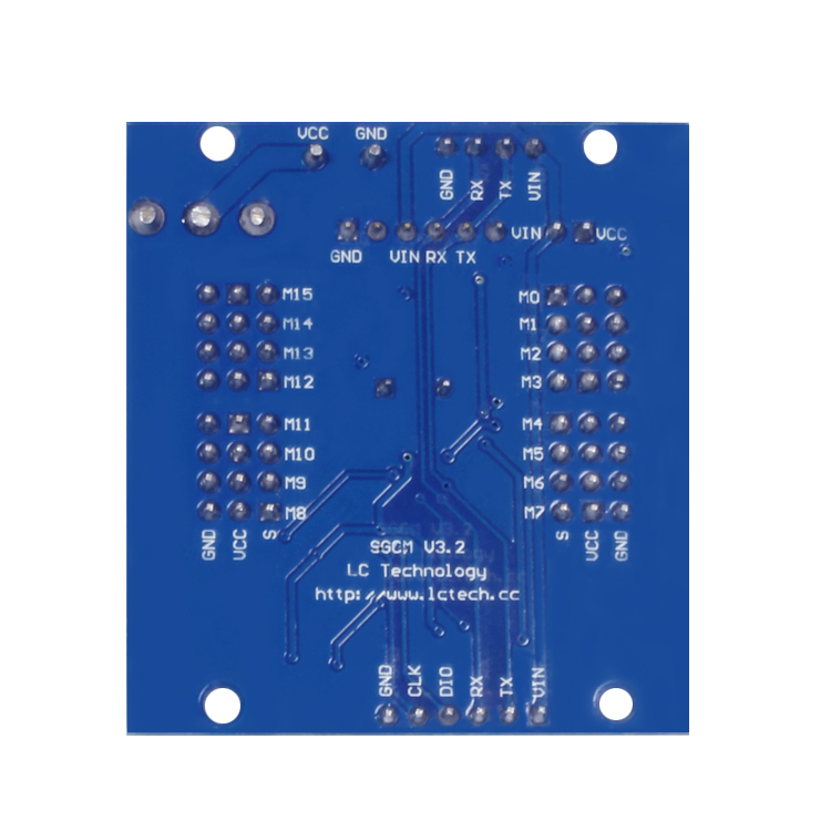
2.Interface specification
VCC、GND: power supply connector of steer gear(exact voltage value refers to specific parameter of steer gear)
VIN、GND: to control separate power supply of chip(no need to connect if use single power supply)
TX、RX: UART Serial communication interface
CLK、DIO: SWD debugging interface
Bluetooth: HC05/06 bluetooth slave computer port
M0-M15: 16ways interface of steer gear port
LED(D1)/LED(D2): indicator of chip power supply/ power supply LED indicator of steer gear
Jumper cap nearby LED(D2): plug in when user single power supply,remove it when use separately
Mode and command format:
This controlling board supports both online and offline working method:
A. The online operation indicates that using the upper computer software or the external MCU directly sends the steering gear position command to control the steering gear in real time.
B. Offline means the steering gear instructions or delay in advance ,which is stored in the on board flash chip, and then through the relevant "off-line control instruction" or buttons to read these instructions and then control the steering gear
Remark :Panel can store 254 offline action group, system allocated storage space for 64 KB to each movement, and each of the "steering gear position instruction" or "delay" directive occupies three bytes, so every action group can contain 2145 "steering gear position instruction" or "delay" command. 2. The insertion delay instruction is supported only offline mode
(1)Format of steer gear position instruction(Character form): #<ch>P<time>!,
a, # means start;
b,<ch>the number of the steering gear controlled, 16 channel in total (range: 00-15 corresponding to M0 and M15 of steering gear )
c,P is indispensable fixed symbol instruction format;
d,<time>is the width of PWM signal (range: 0500-2500 corresponds to 0-180)
e,! Is the end of an instruction 。
For example: send #02P1000!To rotate the steering gear M0 to 45 °
(2)Delay command format(character form): T<time>!,meaning of each character is as below:
a,T means start;
b,<time> delay time(range: 0001-9999,unit: Lms)
c,!End of command
For example:send T0500!To delay 500ms
(3)Command format of online control(hex format):A0 XX YY meaning is as below:
a,A0 start byte;
b,XX functional code,range: 00-05
00 means to reset all the steer gear(that is rotate to 90°),send command A0 00 00;
01 Means to enable the download function of steering gear position or delay instruction (collectively known as action group) ;
02 Represents the download completion, and tells the system that the action group has been downloaded;
03 operate the downloaded action group;
04 stop the action group;
05 delete action group which is stored in flash
c,YY represents code no of action group,range is 01-FE, It's equivalent to 1-254 of decimalism,Note that the maximum value should not exceed FE, because the FF storage space is already occupied by the system.
For example: A0 00 00 reset all the steering gear;
A0 01 01 enable download function of action group one
A0 02 01 disable download function of action group one
A0 03 0F to operate action group 15
A0 04 0F to stop action group 15
A0 05 A5 delete action group 165
Basic specification
1.About power supply: there are two ways of power supply,single powering supply and independent power supply.
(1)When using single-source power supply, plug in the jumper cap, VCC, GND green terminal to connect the power supply to the steering gear (the voltage is subject to the specific power supply range of the steering gear)
(2)Remove the jumper cap when adopt independent power supply,VCC ,GND of green terminals connects to power supply of steering gear (voltage will be subject to specific range of steering gear power supply), then VIN, GND connects to 5-9 v power supply, you can use the USB power supply.
Because the steering gear is a power consumption device, so for steering gear power supply current should be enough.The on board LED is blinking when the steering gear is rotating,it is necessary to change power supply because power is not enough. So,it is better to use separate power supply to keep steer gear stable rotating .