Integrity - based innovation in science and technology Home|Favorite|Contact us
Name:Helen.
Tel:+86-755-82720811
E-mail:helen@chinalctech.com
Add:Room 301,Building No.3,Guole Technopark,Lirong Road,Dalang Street,Longhua District,Shenzhen 518110,China.
Online consultingSKU: LC-Relay-PLC-2R
Overview
Relay isolation drive control module, the core is electronic control devices relay,there are control system ( called input loop) and controlled system (called output loop), Essentially an "automatic switch" that uses a small current to control large currents. This design have output signal indicator prompt,adopt dual power supply selection and optocoupler design, enhance anti-interference and isolation performance. can be used for signal amplification of MCU ,PLC, industrial computer and other equipment.
Function features
1.Adopt HONGFA relay, performance are stable and reliable.
2.Compatible with positive and negative control input modes.
3.Each channel have one indicator prompt, More intuitive understanding of product performance.
4.Each channel adopt Optocoupler isolation, enhance anti-interference and isolation performance.
5.At the same time supply power and IN control terminal was independent control.
6.Module adopt standard “DIN”Rail mounting design, The installation is convenient, fast and stable.
Hardware introduction and description
1.Picture
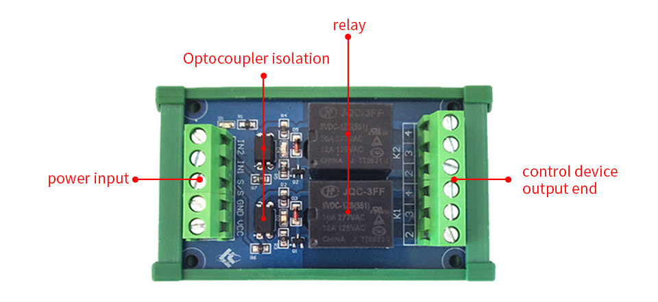
Positive control wiring introduction:
1.Power input terminal: VCC connected to the positive voltage,GND connected to the negative voltage , S/S terminal connected to the positive voltage IN1,IN2 connected to negative voltage control ,INI control KI terminal .IN2 control K2 terminal.
2.Control device output end
On the output circuit board marked 234,3 Representing a common point,2 Representing normally open, 4 Representing normally close.K1 k2 Representing two channel relay working.
© 2011-2024 Shenzhen LC Technology Co.,Ltd. All rights reserved.
Add:Room 301,Building No.3,Guole Technopark,Lirong Road,Dalang Street,Longhua District,Shenzhen 518110,China.
Tel:+86-755-82720811


Mobile station